Signal Detector with Calibration Circuit Arrangement

a signal detector and circuit arrangement technology, applied in the field of signal detection circuits, can solve the problems of invalid data, system errors, and inability to reliably detect signals, and achieve the effect of eliminating the inherent differential signal imbalan

Active Publication Date: 2007-11-22
MARVELL ASIA PTE LTD
View PDF13 Cites 20 Cited by
  • Summary
  • Abstract
  • Description
  • Claims
  • Application Information

AI Technical Summary

Benefits of technology

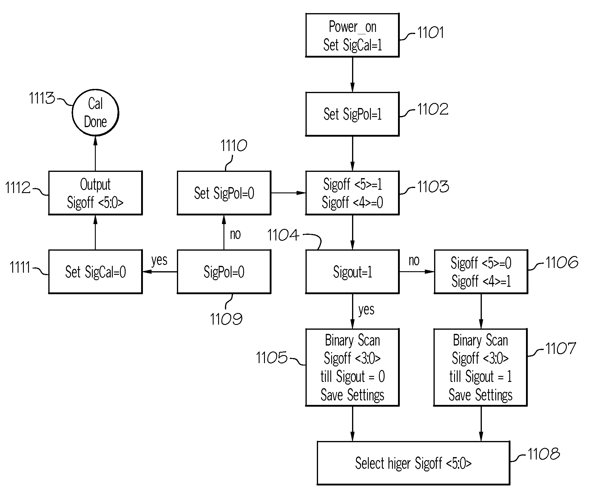
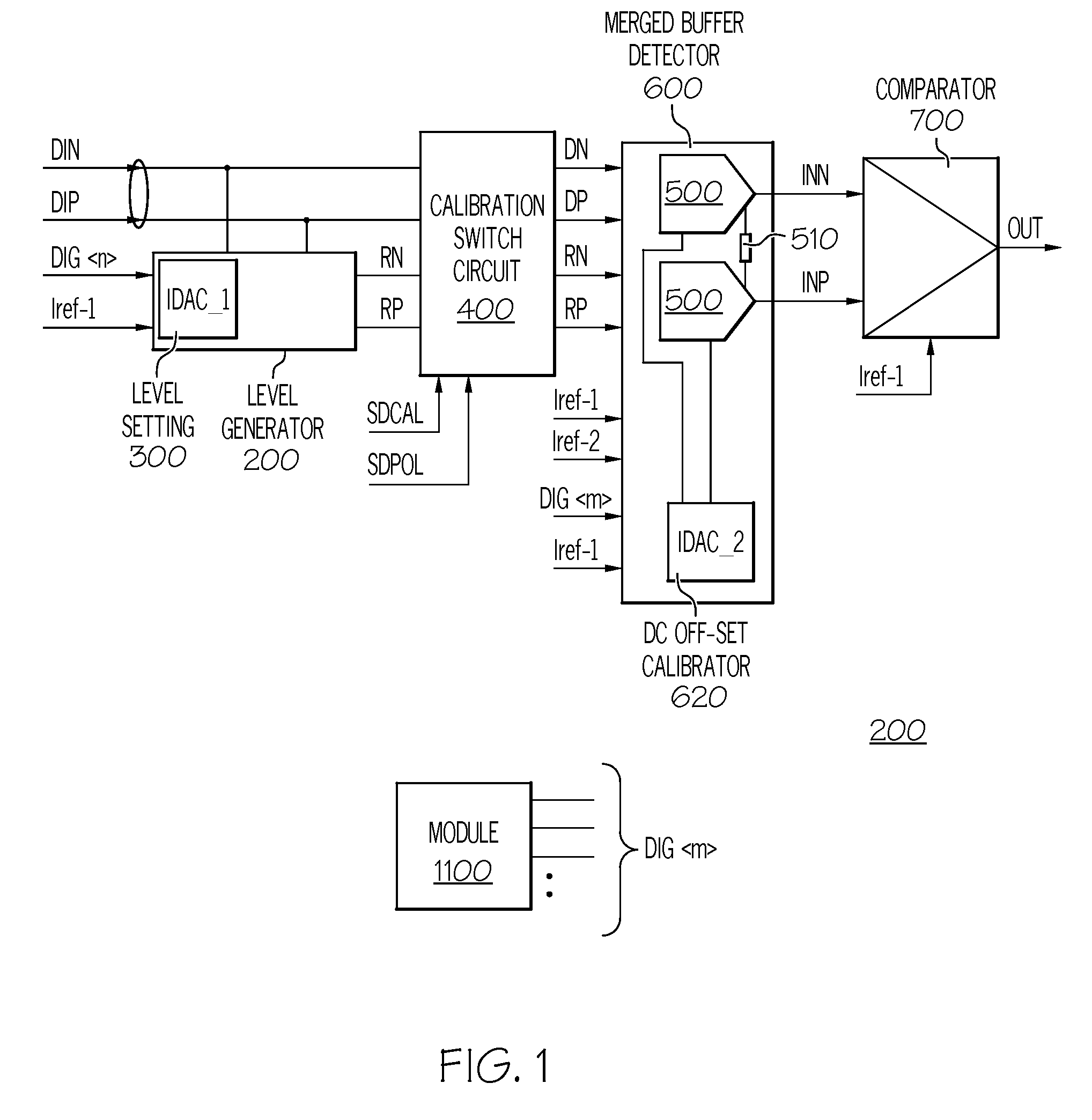
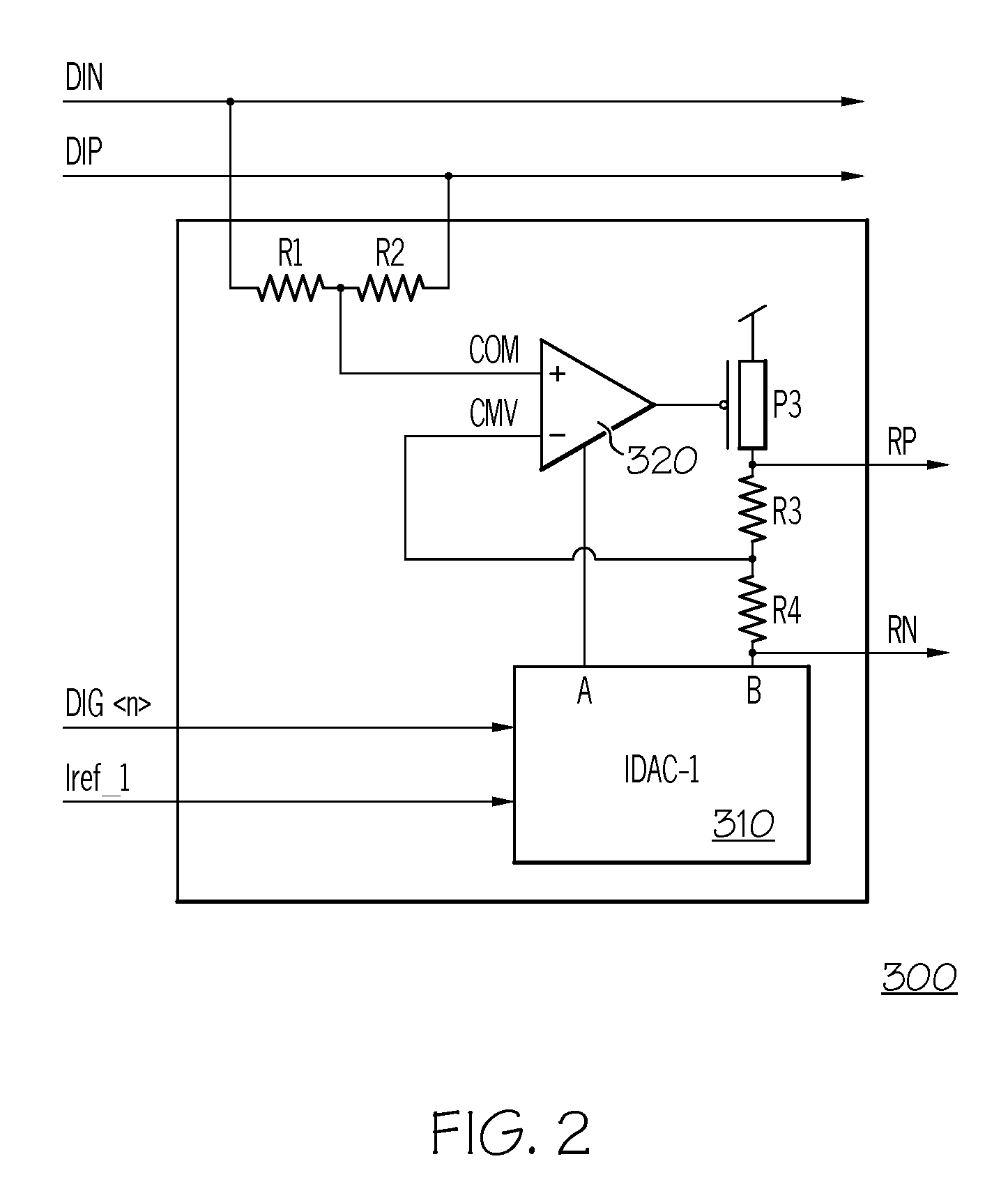
[0017]The invention also describes method for calibrating the signal detector. According to an aspect of the method, during power on or other selected interval, the signal detector is calibrated by IDAC-2 off-set calibrator using a known internal reference level signal provided by the level generator / IDAC-1 level setting generator. The purpose of the calibration is to eliminate the inherent differential signal imbalance due to device mismatch, including device size difference between two differential pairs, mirror devices, load resistors, threshold mismatch of a pair of matching sensitive devices, etc.

Problems solved by technology

Unless the conductors attached at the input to the receiver are carrying a “good” serial data signal, resources and time could be wasted by the receiver processing invalid or unreliable input.
Furthermore, invalid data has the potential of causing system errors.
A “bad” signal can also occur if the signal conductors become damaged or temporarily interrupted.
When loss-of-signal occurs, some types of receivers that are equipped with an automatic gain control (AGC) loop incorporated with a decision feedback equalizer (“DFE”) feature may incorrectly attempt to restore the signal by increasing the gain at the receiver's front end.
However, the system disclosed in that article is not robust, possibly falsely detecting a good signal when a voltage or current spike appears, and having difficulty detecting valid signals in systems having a serial data transmission rate of 5 Gbs and higher.
A disadvantage of the system described in the '082 patent is that it cannot proceed without having recovered a good clock from the input data signal at the beginning of a data communication period.
However, if the input signal is bad from the beginning, the clock may not be present or may be unreliable and incapable of accurately sampling the input signal, making the loss-of-signal detector fail to work at all.
Another problem of the system described in the '082 patent is that it only permits a fixed signal threshold level setting for detecting loss-of-signal.
As a result, in communication systems using SerDes cores, a good signal threshold for one system can sometimes resemble noise in others.
As in the above system described in the '082 patent, this system also cannot operate over the wide range of signal frequencies and voltage levels that are desirable for SerDes cores.

Method used


Image

  • Signal Detector with Calibration Circuit Arrangement
  • Signal Detector with Calibration Circuit Arrangement
  • Signal Detector with Calibration Circuit Arrangement

Examples


Embodiment Construction

[0028]Designing a robust signal detector to meet a wide range of customer specifications is definitely not an easy task. The task includes the requirement of detecting incoming signals with a narrow signal amplitude window and spanning wide ranges of signal frequency, common mode level, supply voltage, and operating temperature. The goal is to design a single signal detector that fits these and other requirements. The one design fits all is certainly an ideal goal in an ASIC environment to save development, manufacturing, testing and maintenance cost. Some customer specifications have a very small margin separating valid signal amplitude from noise. For example, in the Infiniband architecture specification, signal and noise peak-to peak amplitudes are defined as 87.5 mV and 42.5 mV, respectively. In other words, a signal detector must detect the presence of valid signal when the incoming signal has a peak-to-peak amplitude greater than 87.5 mV. On the other hand, it must detect abse...


PUM


Abstract

A signal detector and method detect the presence or absence of an incoming differential signal. The method nullifies the DC off-set of the signal detector so that it can detect a signal within a very narrow window. The common mode levels of the signal and reference paths are used for calibration which is done automatically by use of an embedded algorithm residing in a digital block. The calibration range and resolution are predetermined to cope with the technology, modeling, design methodology and human error.

Description

CROSS REFERENCE TO RELATED APPLICATION[0001]The present application is related to commonly owned, co-pending U.S. patent application Ser. No. 10 / 604,799 entitled “Apparatus and Method for Detecting Loss of a High Speed Signal” and Ser. No. 10 / 905,704 entitled “Improved Signal Detector for High Speed Serdes”. Both patent applications, in their respective entirely, are incorporated by reference as if fully set forth herein.FIELD OF THE INVENTION[0002]The present invention relates to signal detection circuits in general and in particular to circuits for detecting both presence and absence of incoming differential signals in duplex Serdes (Serial-Deserialize) communications links.BACKGROUND OF THE INVENTION[0003]In contemporary high-speed serial data communications, a duplex high-speed serial (HSS) communication link is typically implemented by an integrated circuit (“IC” or “chip”) that includes at least one pair of a serializer (transmitter) and a deserializer (receiver) on the same c...

Claims


Application Information

Patent Timeline
Patent Type & Authority Applications(United States)
IPC IPC(8): G06F19/00
CPCH04L25/0296H04L25/0274
Inventor CHEN, MINHANHSU, LOUISNATONIO, JOSEPHSELANDER, KARL D.SORNA, MICHAEL A.ZIER, STEVEN J.
Owner MARVELL ASIA PTE LTD
Why Eureka
Try Eureka