Apparatus and method for fastening together structural components

a technology of structural components and apparatus, applied in the field of apparatus and methods for fastening together structural components, can solve the problems of operator fatigue, slow pre-drilled hole procedure, and insufficient reliability of prior electric powered screw driving systems using self-drilling wing screws,

Active Publication Date: 2007-11-29
HAYTAYAN HARRY M
View PDF69 Cites 16 Cited by
  • Summary
  • Abstract
  • Description
  • Claims
  • Application Information

AI Technical Summary

Benefits of technology

[0015] These and other objects are achieved by providing a tool that comprises an electrically powered rotary driver with means for supporting and rotatively driving a screw driver tool bit that is adapted to make a locking engagement with the head of a screw fastener, a magazine for supporting a strip of screw self-drilling, self-tapping fasteners, a pneumatically-powered telescoping driver support/fastener positioning means comprising a fastener positioning member for receiving individual fasteners from the magazine in a position to be driven and telescoping means conn

Problems solved by technology

That procedure using predrilled holes is slow due to the need to pre-drill the members to be secured together.
Prior electric powered screw driving systems using self-drilling wing screws have not been satisfactory for reliably, effectively and rapidly penetrating such high tensile strength frame members with self-drilling, self-tapping screws, and there use in such applications has been limited to screws with a maximum shank diameter of about 6 mm, exclusive of the wings, and a maximum head diameter of about 11 mm.
In addition to the screws not readily penetrating the HTS steel and the screw driving process being slow (about 25 seconds), a significant limiting factor is that driving the fasteners requires the operator to exert a substantial downward force on the driver in order for the screw driver bit to drive the fastener into the high tensile strength frame member, which leads to operator fatigue.
It is to be noted that also using an electric screw driver with a greater speed, e.g., 5000 rpm, has been found to be unacceptable since at that higher speed the heat buildup at the interface of the screws with the HTS steel frame member will cause the tips of the screws to burn up, which in turn reduces the ability of the drill po

Method used


Image

  • Apparatus and method for fastening together structural components
  • Apparatus and method for fastening together structural components
  • Apparatus and method for fastening together structural components

Examples


Embodiment Construction

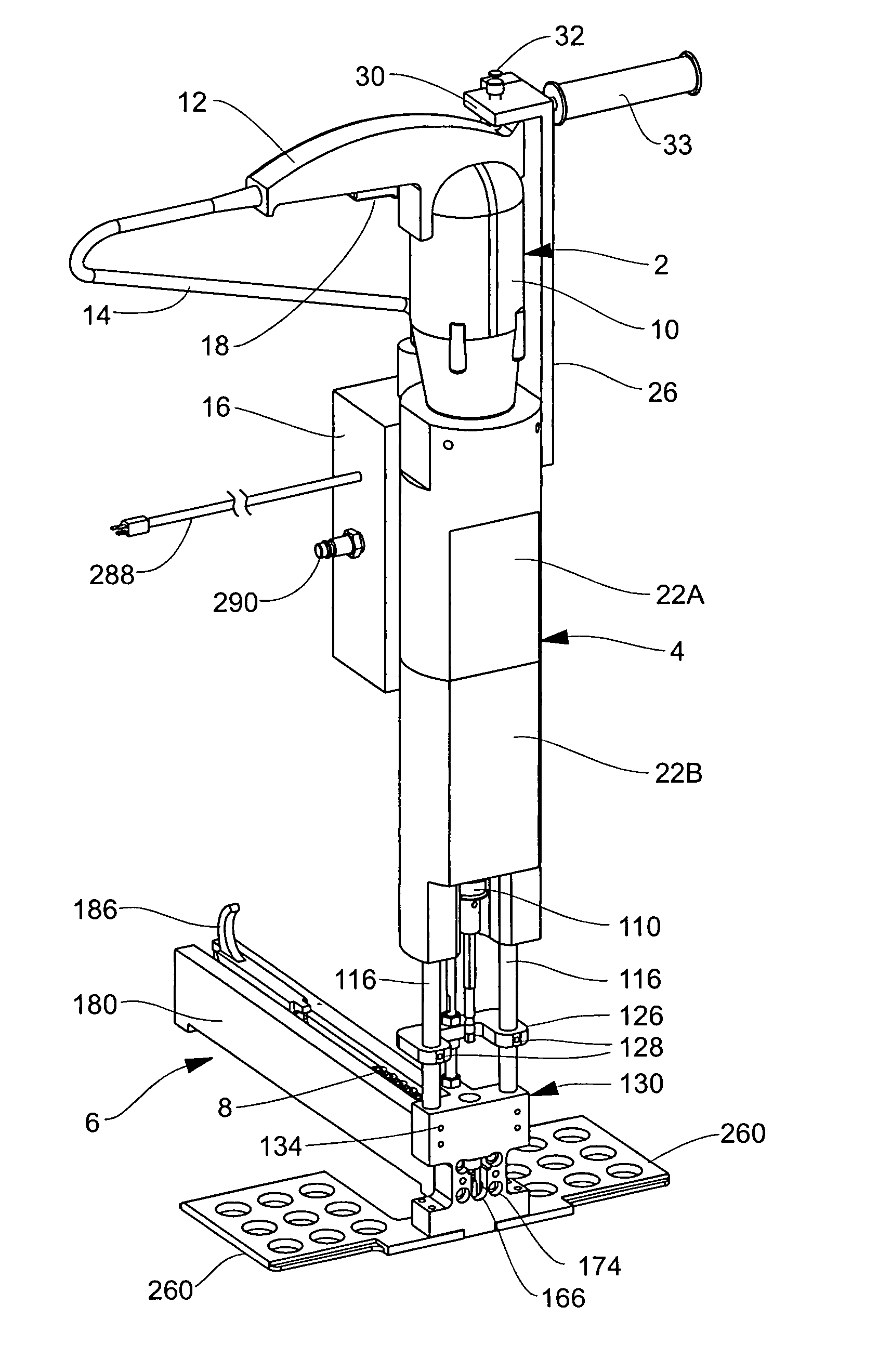
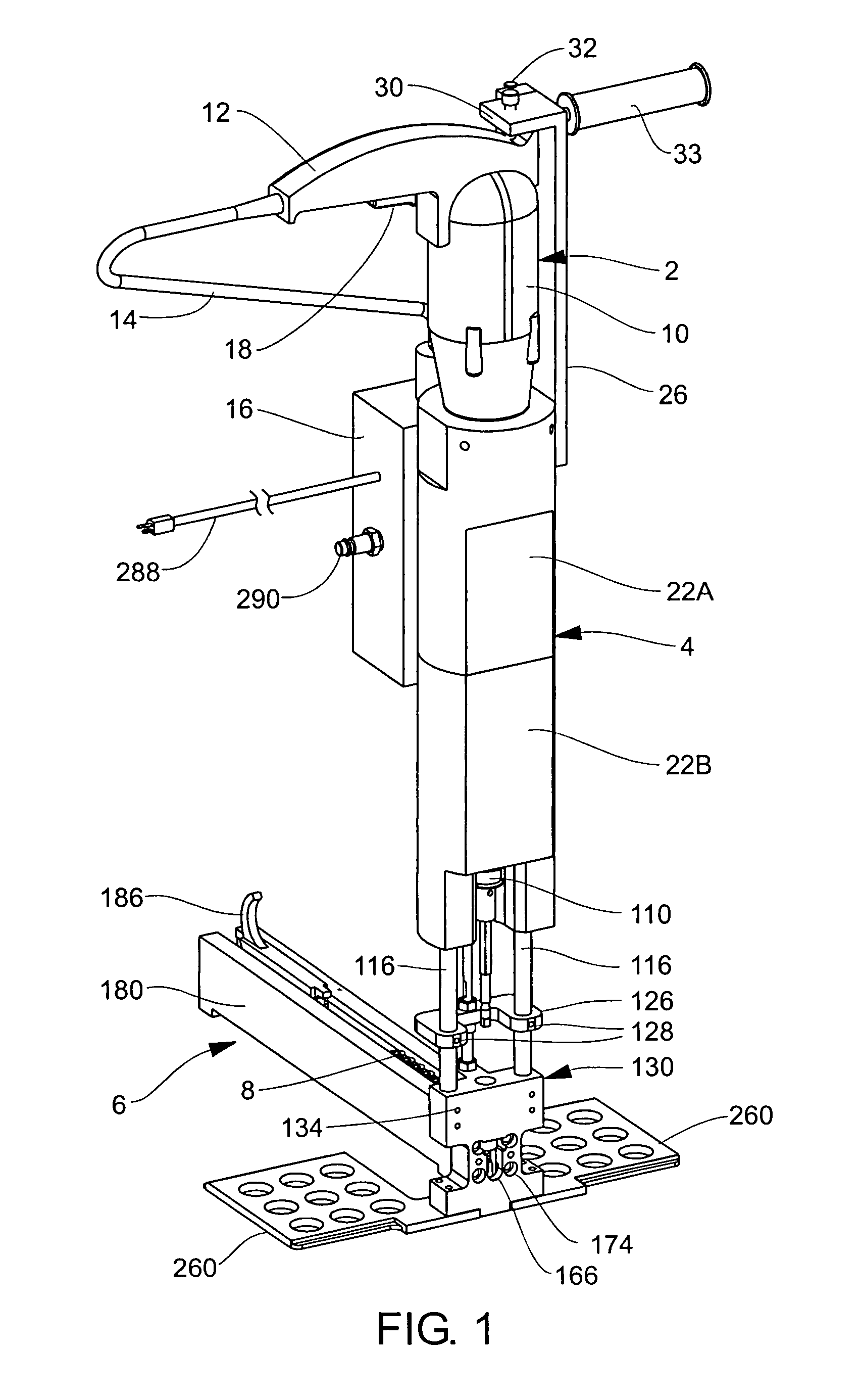
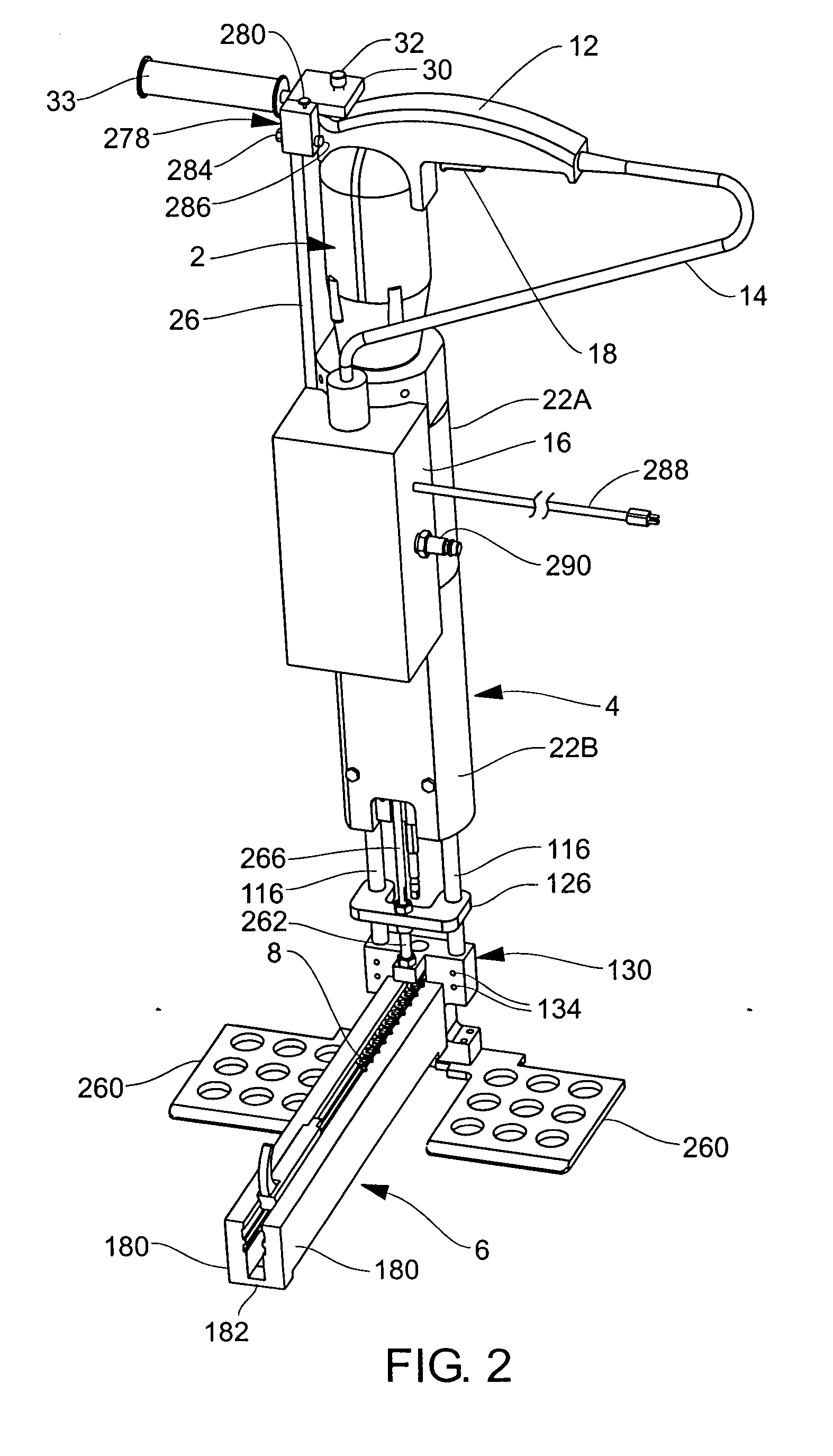
[0037] Referring to FIGS. 1-4, the illustrated apparatus includes and utilizes an electrically-powered rotary driver 2 (“electric driver”) that preferably, but not necessarily, is adapted to operate in both forward and reverse directions. Electric drivers are made and sold by numerous companies. The rotary output shafts of such drivers are commonly fitted with means, e.g. chucks, for securely attaching thereto drills, screw driver bits, brushes or other tools.

[0038] Still referring to FIGS. 1 and 2, the electric driver 2 is attached to a telescoping driver support / fastener positioning unit 4 to which is attached a magazine 6 that carries a supply of fasteners 8 as hereinafter described. Driver 2 has a housing 10 and a handle 12 that is provided with an electric power cord 14 for attaching the driver to a source of electric power via a control system hereinafter identified and described that is contained in a box 16 mounted on the unit 4. Preferably the driver's electric motor is ad...


PUM

PropertyMeasurementUnit
Forceaaaaaaaaaa
Pressureaaaaaaaaaa
Flow rateaaaaaaaaaa

Abstract

An apparatus and method for fastening a wood panel to a high structural strength steel frame member using self-drilling, self-tapping screws. An electrically powered rotary driver with an attached screw driver bit is carried by a pneumatically-powered telescoping driver support/fastener-positioning unit that includes a fastener positioning plate, telescoping members attached to the fastener positioning plate, and a pair of foot plates for the operator to stand on whereby to hold the apparatus down during a screw-driving operation. The driver and the driver support/fastener-positioning unit are controlled by an electro/pneumatic system. The method implemented by that system comprises retracting the driver support/fastener positioning unit so as force the screw driver bit to engage in the positioning plate, operating the driver as the telescoping members are retracted so that the screw driver bit will cause the engaged fastener to drill in turn through the wood panel and the steel frame member and form a screw connection with the steel frame member, and then turning off the driver and re-extending the telescoping members so as disengage the screw driver bit from the driven fastener, ready for a new screw-driving operation.

Description

[0001] This is a continuation-in-part of copending U.S. patent application Ser. No. 11 / 168,852, filed 28 Jun. 2005, which is a division of U.S. application Ser. No. 10 / 619,374, filed 11 Jul. 2003 (now U.S. Pat. No. 6,990,731), which is a continuation-in-part of U.S. application Ser. No. 10 / 195,207, filed 15 Jul. 2002 (now abandoned) for “Method And Apparatus For Attaching Structural Components With Fasteners.FIELD OF THE INVENTION [0002] The present invention generally relates to a novel apparatus and method for fastening structural elements together with screw fasteners. BACKGROUND OF THE INVENTION [0003] It is well known to use screws and nails, or similar pin-type fasteners, for securing floor, wall and ceiling panels to supporting structures in buildings and vehicle cargo container bodies. In the case of truck trailer and cargo container bodies, hard wood floors are attached to a steel metal frame or substrate with screw fasteners. It is essential that those screws be driven in ...

Claims


Application Information

Patent Timeline
IPC IPC(8): B23P11/00
CPCF16B27/00B25B21/002Y10T29/49833Y10T29/53487B25B23/045
Inventor HAYTAYAN, HARRY M.
Owner HAYTAYAN HARRY M
Why Eureka
Try Eureka