Barrier metal film production method

a production method and metal film technology, applied in the direction of coatings, decorative arts, chemical vapor deposition coatings, etc., can solve the problems of insufficient burial of depressions, uneven directionality, and damage to substrates, so as to reduce the number of plasma sources, simplify the supply line of gases, and improve the adhesion

Inactive Publication Date: 2007-11-29
CANON ANELVA CORP
View PDF40 Cites 5 Cited by
  • Summary
  • Abstract
  • Description
  • Claims
  • Application Information

AI Technical Summary

Benefits of technology

[0068] Thus, a barrier metal film comprising a film of a metal nitride and a metal film and with diffusion suppressed and adhesion improved can be prepared by forming a metal by plasmas. The barrier metal film can be formed uniformly to a small thickness. Also, the supply line for gases can be simplified, and the number of plasma sources can b

Problems solved by technology

However, the barrier metal film has been produced by use of sputtering, and its directionality is not uniform.
With a tiny depression on the surface of the substrate, therefore, the film is

Method used


Image

  • Barrier metal film production method
  • Barrier metal film production method
  • Barrier metal film production method

Examples


first embodiment

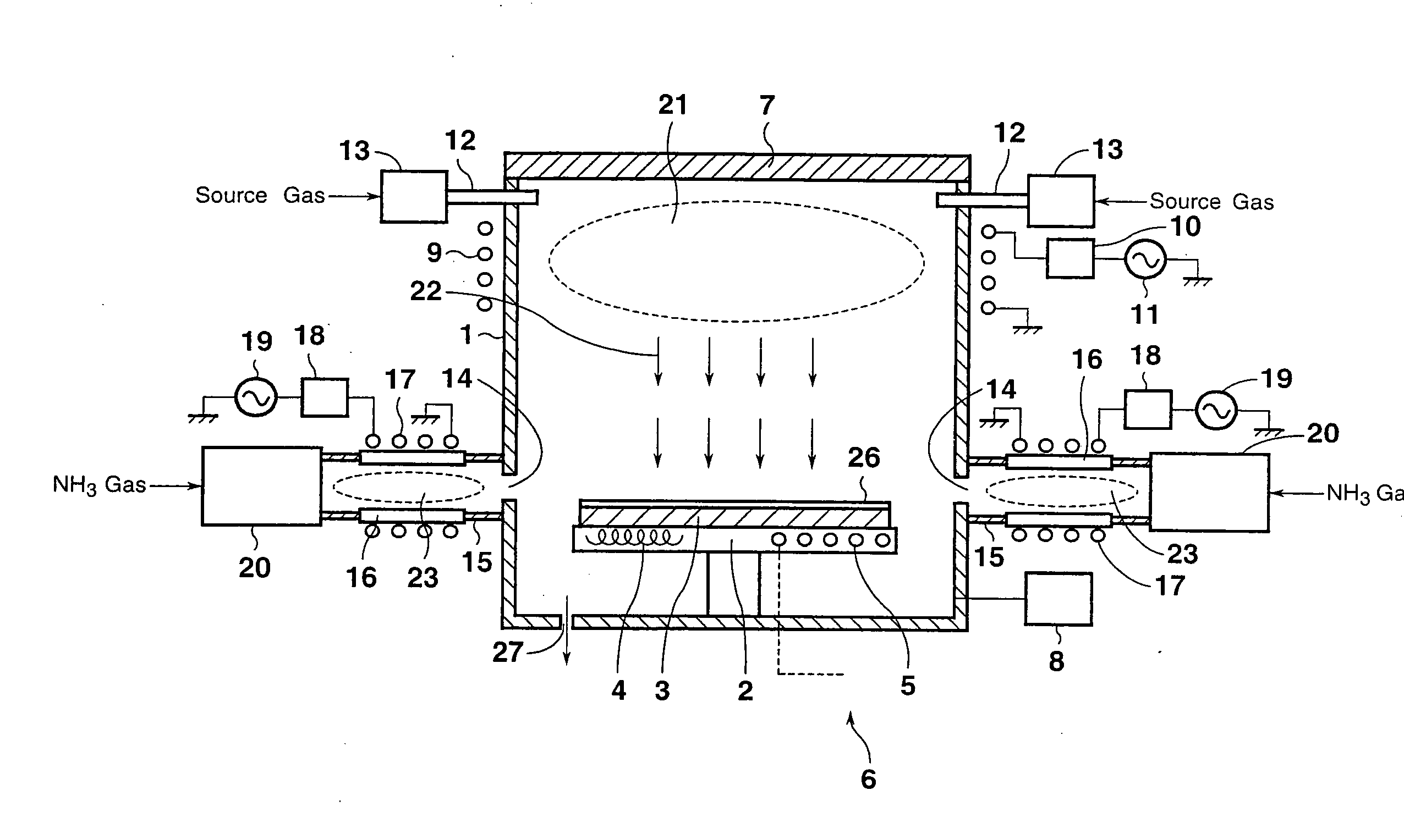
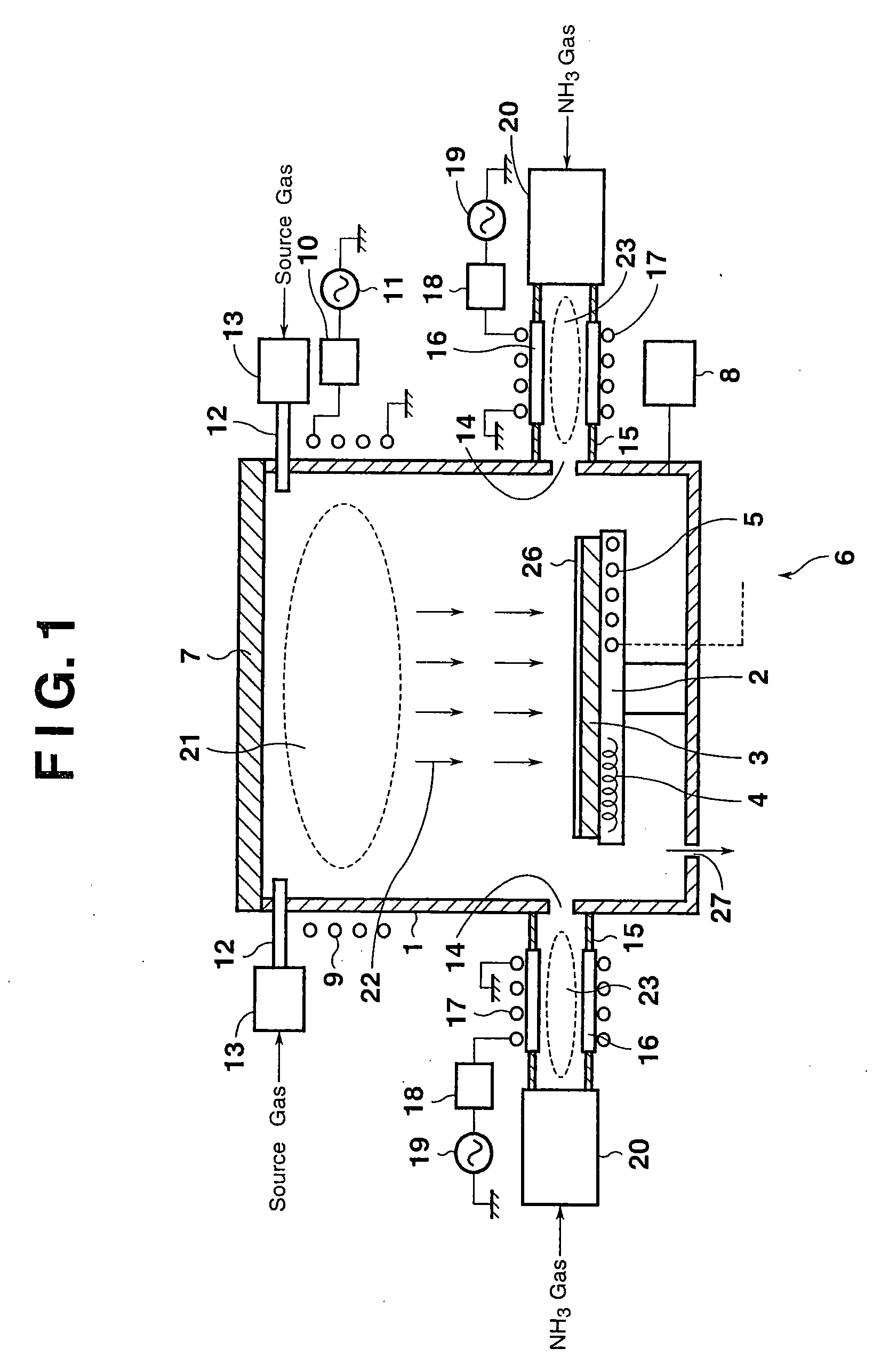
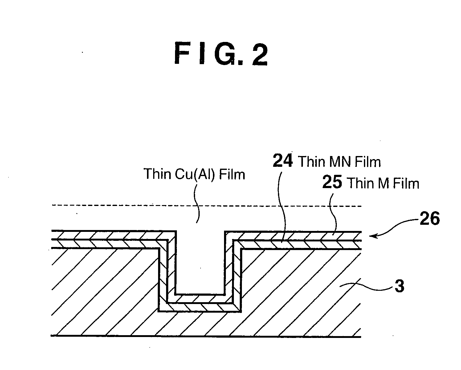
[0108] With the above-described barrier metal film production apparatus, similar to the first embodiment, the metal is formed by plasmas to produce the barrier metal film 26. Thus, the barrier metal film 26 can be formed uniformly to a small thickness. Consequently, the barrier metal film 26 can be formed highly accurately at a high speed with excellent burial properties in a very small thickness even to the interior of a tiny depression, for example several hundred nanometers wide, which has been provided in the substrate 3.

[0109] In addition, the etched member 31 has the plurality of protrusions 33 provided in the circumferential direction on the inner periphery of the ring portion 32, and includes the notches (spaces) 35 formed between the protrusions33. Thus, the induced currents generated in the etched member 31 flow in the same direction as the flowing direction of electricity in the plasma antenna 34, when viewed from the substrate 3. Therefore, even though the etched member ...

second embodiment

[0141] With the above-described barrier metal film production apparatus, the same effects as in the second embodiment are obtained. In addition, the supply line for the gases can be simplified, and the number of the plasma sources can be decreased. Thus, the cost of the product can be reduced.

[0142] The seventh embodiment of a barrier metal film production apparatus and a barrier metal film production method according to the present invention will be described with reference to FIG. 10. FIG. 10 is a schematic side view of the barrier metal film production apparatus according to the seventh embodiment of the present invention. The same members as in the third and fifth embodiments illustrated in FIGS. 6 and 8 are assigned the same numerals, and duplicate explanations are omitted.

[0143] Compared with the third embodiment shown in FIG. 6, the barrier metal film production apparatus shown in FIG. 10 lacks the opening portion 14, passage 15, excitation chamber 16, plasma antenna 17, mat...

third embodiment

[0148] With the above-described barrier metal film production apparatus, the same effects as in the third embodiment are obtained. In addition, the supply line for the gases can be simplified, and the number of the plasma sources can be decreased. Thus, the cost of the product can be reduced.

[0149] The eighth embodiment of a barrier metal film production apparatus and a barrier metal film production method according to the present invention will be described with reference to FIG. 11. FIG. 11 is a schematic side view of the barrier metal film production apparatus according to the eighth embodiment of the present invention. The same members as in the fourth embodiment and the fifth embodiment illustrated in FIGS. 7 and 8 are assigned the same numerals, and duplicate explanations are omitted.

[0150] Compared with the fourth embodiment shown in FIG. 7, the barrier metal film production apparatus shown in FIG. 11 lacks the opening portion 14, passage 15, excitation chamber 16, plasma an...


PUM


Abstract

A Cl2 gas plasma is generated at a site within a chamber between a substrate and a metal member. The metal member is etched with the Cl2 gas plasma to form a precursor. A nitrogen gas is excited in a manner isolated from the chamber accommodating the substrate. A metal nitride is formed upon reaction between excited nitrogen and the precursor, and formed as a film on the substrate. After film formation of the metal nitride, a metal component of the precursor is formed as a film on the metal nitride on the substrate. In this manner, a barrier metal film with excellent burial properties and a very small thickness is produced at a high speed, with diffusion of metal being suppressed and adhesion to the metal being improved.

Description

[0001] This is a Continuation-In-Part of U.S. application Ser. No. 11 / 252,811, filed Oct. 19, 2005, now pending, which is a Divisional of U.S. application Ser. No. 10 / 277,733, filed Oct. 23, 2002, now abandoned, with claims the benefits of Japanese Patent Application No. 2002-44296 filed on Feb. 21, 2002, Japanese Patent Application No. 2002-44289 filed on Feb. 21, 2002, Japanese Patent Application No. 2002-027738 filed on Feb. 5, 2002, and Japanese Patent Application No. 2001-348325 filed on Nov. 14, 2001, the entire disclosures of all are incorporated herein by reference in their entirety.BACKGROUND OF THE INVENTION [0002] 1. Field of the Invention [0003] This invention relates to a production method for a barrier metal film to be formed on the surface of a substrate for eliminating the diffusion of a metal into the substrate, when a metal film is formed on the surface of the substrate. [0004] 2. Description of Related Art [0005] Semiconductors with electrical wiring have increasi...

Claims


Application Information

Patent Timeline
IPC IPC(8): B44C1/22H01L21/311
CPCC23C16/34C23C16/452H01L21/76843H01L21/28556H01L21/32051C23C16/50
Inventor SAKAMOTO, HITOSHIYAHATA, NAOKIMATSUDA, RYUICHIOOBA, YOSHIYUKINISHIMORI, TOSHIHIKO
Owner CANON ANELVA CORP
Why Eureka
Try Eureka