Insulated rail joint assembly

a joint assembly and rail technology, applied in rail devices, roads, constructions, etc., can solve the problems of increasing the deflection at the weaker part of the rail, affecting the strength of the rail, so as to achieve the effect of improving strength and simple construction

Active Publication Date: 2007-11-29
VOESTALPINE RAILWAY SYST NORTRAK LLC
View PDF19 Cites 20 Cited by
  • Summary
  • Abstract
  • Description
  • Claims
  • Application Information

AI Technical Summary

Benefits of technology

[0014]It is a further object of the invention to provide an insulating rail joint assembly with improved strength and simple construction.

Problems solved by technology

The prior art arrangement gives rise to certain difficulties.
Downward forces from passing trains deflect the rail, and tend to cause greater deflection at the weaker part of the rail, namely the joint.
Glue at the bond lines of the joint creates a weak point, which is susceptible to cracking and failure.
The bond lines are also weak under thermal loads.
As the ambient temperature changes, the rails contract and expand, creating a shear force along the bond lines, which in turn causes joint slip and failure.
Failure of the separator between the rail ends will decrease the insulating properties of the joint, leading to possible short circuits along the track.
In addition, shorts between the joint bar and the rail can occur if the glue and insulating material between those pieces fails under repeated deflections.
Bar-to-rail shorts are also a concern if uninsulated metal fasteners are inserted through bars and the rail web to hold the bars in place, or if the insulating means fail.
However, while locating the joint over a tie helps support the joint, electrical shorts may be caused when the joint comes in contact with a typical steel tie plate.
As noted above, another concern is the failure of a rail joint along the bond line between the rail web and the joint bars.
However, the addition of another layer at the bond line often simply provides another plane along which the joint can fail.
Urmson Jr. recognizes that the adhesive layer is often compressed too much when the joint bars are tightened around the rail web, which tends to crush the matting and squeeze much of the adhesive out of the joint, thereby weakening the bond and adversely affecting the insulating properties.
The use of through-bolts or other fasteners to secure the joint bars in place on the rail webs may cause another weakness in the joint, namely the potential for failures and stresses around the holes through the rail web.
This means that stresses tend to concentrate around the holes through the narrow rail web, leading to cracks and other imperfections, followed by failure of the rail web.
Failure of the rail through cracking and failure of the web around a bolt hole is often a problem.
The fasteners which hold the joint bars in place on the rail webs are also subject to stresses and may fail.
However, neither of these patents discloses a mechanism to protect these bushings from failure, or to ensure that the bolt is still insulated from the rail and joint bars should the bushing fail during use.
As noted above, while it may be preferable to fully support the rail joint with a cross tie, this arrangement can cause difficulties in that a metal tie plate or a steel cross tie may electrically short circuit with the rail.
However, this method is relatively complex and expensive, as the specially manufactured ties must be placed at the correct positions during the track laying process.

Method used


Image

  • Insulated rail joint assembly
  • Insulated rail joint assembly
  • Insulated rail joint assembly

Examples


Embodiment Construction

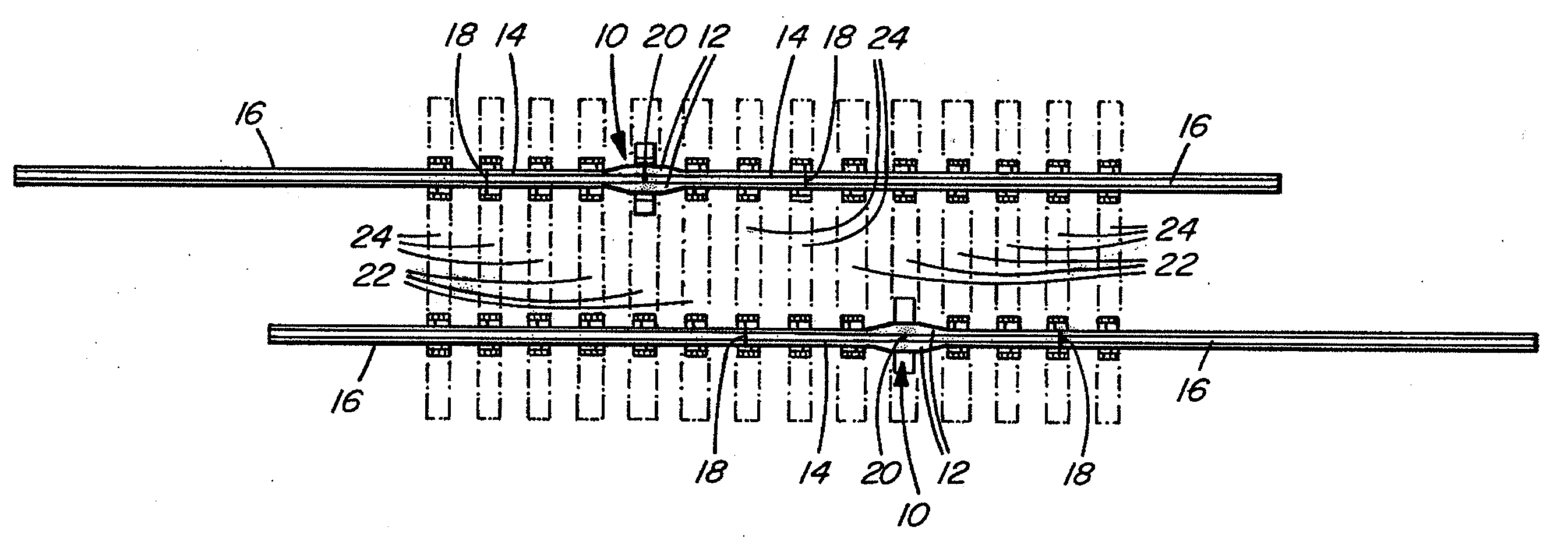
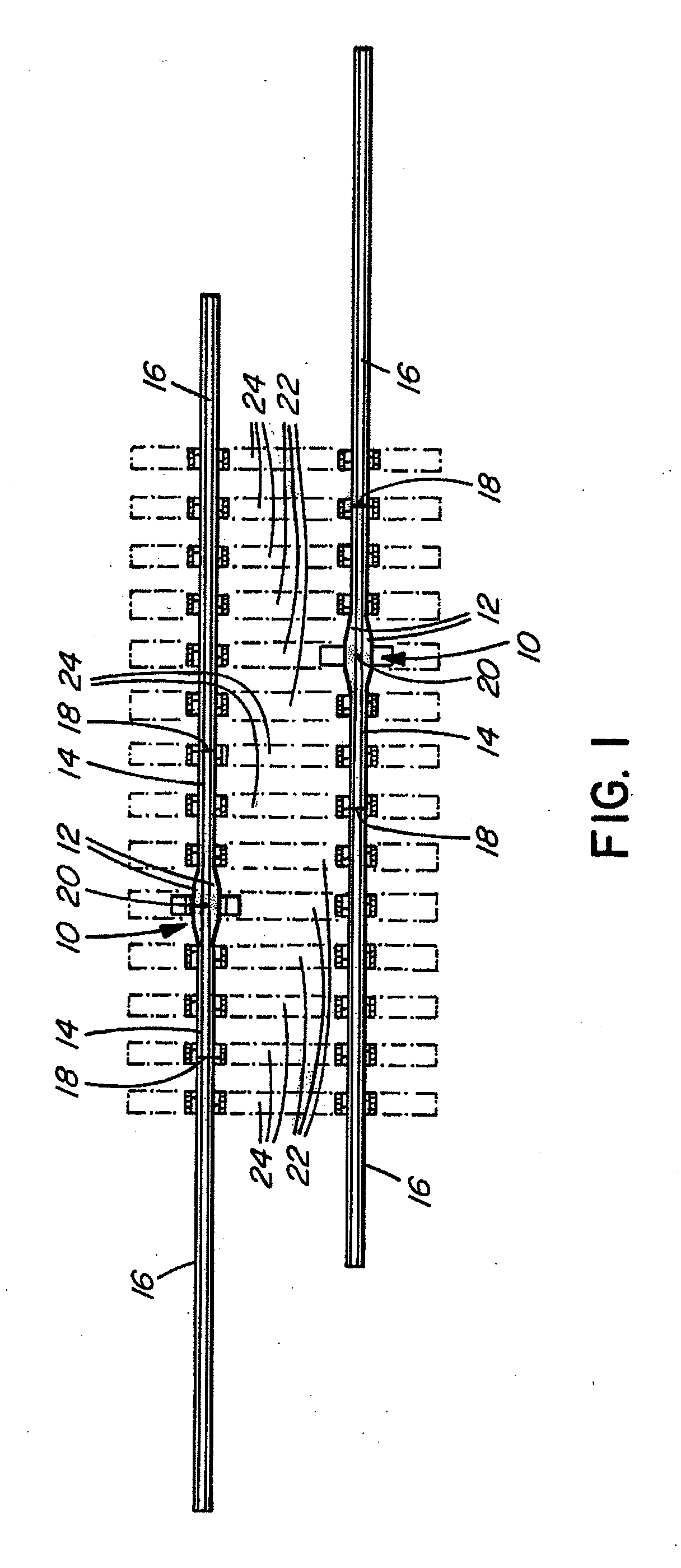
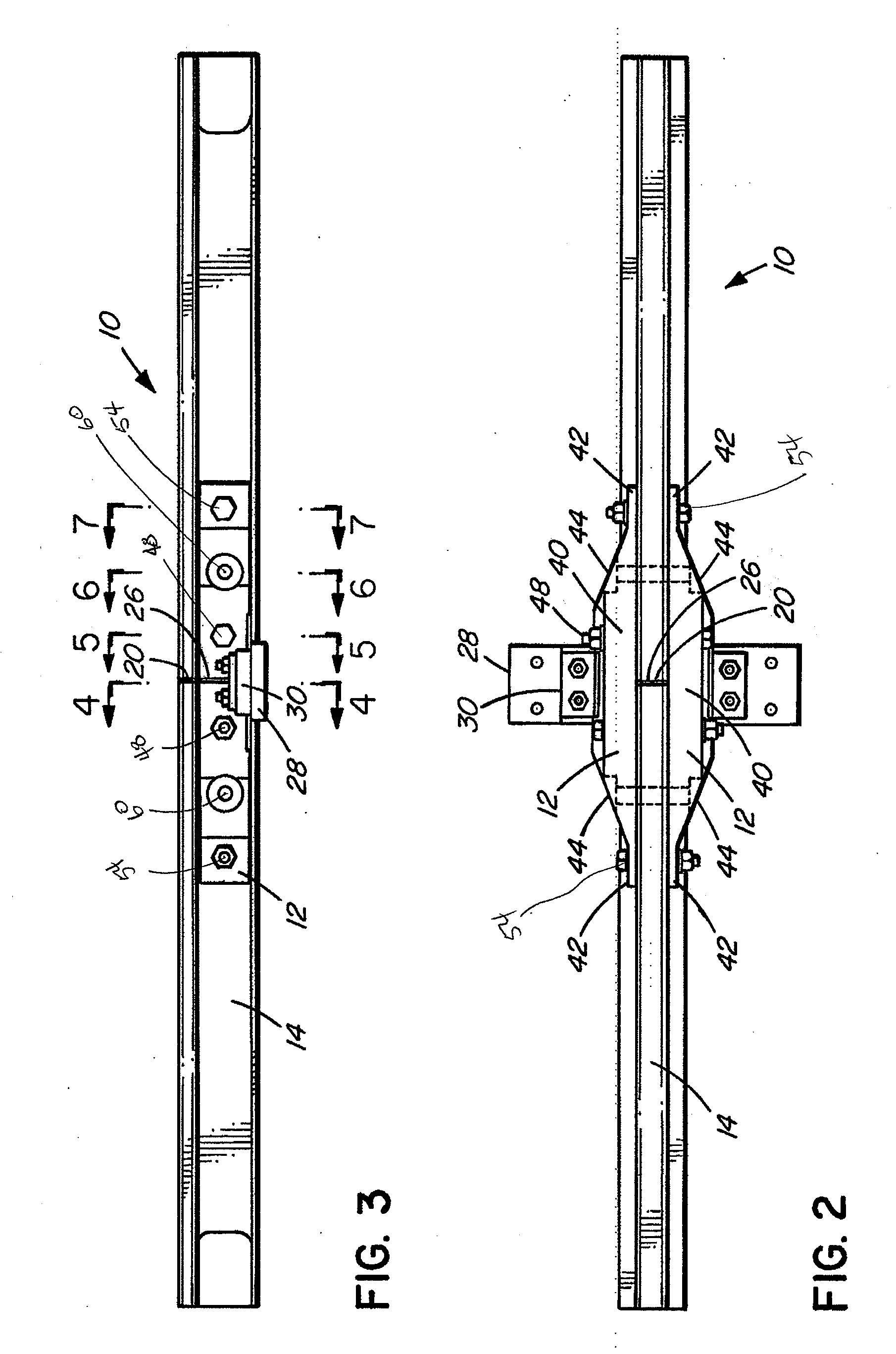
[0045]FIG. 1 shows the preferred embodiment of the insulated rail joint assembly 10 inserted into a standard railway track. The insulated joint assembly comprises two rail segments 14 and one or two joint bars 12, the joint bars 12 being fastened to and extending between the respective web portions 64 of said first and second rail segments 14. The joint bars 12 are installed at the abutment of the rail segments 14, against the web 64, and between the feet 68 and heads 70 of the rail segments 14. Rail segments 14 preferably have thick webs, relative to the pre-determined web thickness of the running rails 16. For example, in North America, standard running rails typically have web thicknesses ranging between ⅝″ and ¾″. Rail segments 14 preferably have web thicknesses of approximately 1.5 to 2.5 times the thickness of the running rails 16. For example, 136 TW rail segments may be used in an insulated joint assembly that is to be used between running rails having a web thickness of ⅝″ ...


PUM


Abstract

An insulated rail joint assembly comprises a rail with a thick web section, held in place by joint bars and secured with electrically isolated fasteners. The joint bars have non-uniform cross-sections, being shaped with a thicker midsection area and thinner ends. Electrically non-conductive shear pins through the rail and the joint bars provide shear resistance and prevent glue bond failure. High strength cloth between the rail ends and between the rail and the joint bars strengthens the joint, as does an insulating rail clip resiliently fastened to an insulating tie plate, which itself may be supported on a cross tie of increased width.

Description

TECHNICAL FIELD OF THE INVENTION[0001]This invention relates to an insulated rail joint assembly for use in railway track systems.BACKGROUND OF THE INVENTION[0002]A rail joint assembly connects adjacent rail sections together by mechanically splicing the rail ends. Prior art joint assemblies typically involve joint bars placed along the rails across the joint, on either side of the webs and secured by glue and / or bolts. A separator such as an end post, a gasket or other spacer may be placed between the rail ends. Reinforcing fiberglass cloth may be placed into the bond line between the rail ends and between the joint bar and rail to strengthen and insulate the joint.[0003]Some applications require electrical insulation through the rail joint, such as for signaling, track movement or train location purposes. In those applications, insulating materials are used as separators between the rail ends, and may be also used to separate the joint bars from the rails.[0004]One typical rail jo...

Claims


Application Information

Patent Timeline
Patent Type & Authority Applications(United States)
IPC IPC(8): B60M5/00
CPCE01B11/54
Inventor CLICK, GARYDUFFNER, BRENT
Owner VOESTALPINE RAILWAY SYST NORTRAK LLC
Why Eureka
Try Eureka