Dual Bypass for Piston-Type Flushometer

Inactive Publication Date: 2007-11-29
SLOAN VALVE COMPANY
View PDF33 Cites 26 Cited by
  • Summary
  • Abstract
  • Description
  • Claims
  • Application Information

AI Technical Summary

Benefits of technology

[0007] The provision of at least a second bypass orifice reduces the clogging risk associated with a single bypass orifice and a piston according to the present invention provides additional benefits. For example, the importance of the angular orientation of the piston is greatly reduced, because there is always a bypass orifice no more than 90° away from the inlet connection. This simplifies assembly of the valve, because the piston does not have to be installed in any particular alignment. Also, the upper pressure chamber is more consistently vented and the influence of fixture-induced back pressure in the valve is reduced, which permits a more accurate flush. Furthermore, water travel distance from the filter to a bypass orifice is reduced, whi

Problems solved by technology

In order for the flush valve to work properly, the bypass orifice must remain unclogged and functional, otherwise insufficient fluid flow will be allowed into a pressure chamber above the piston assembly and the valve will not close as intended.
One disadvantage of a filtered bypass orifice is that the filter can allow irregularly-shaped particulates to pass through which may later clog the downstream orifice.
Another disadvantage is that the fil

Method used


Image

  • Dual Bypass for Piston-Type Flushometer
  • Dual Bypass for Piston-Type Flushometer

Examples


Embodiment Construction

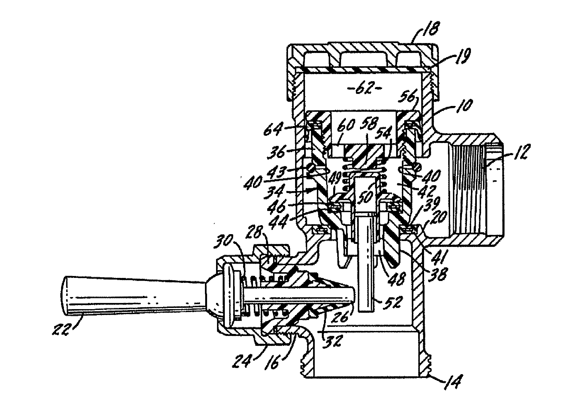
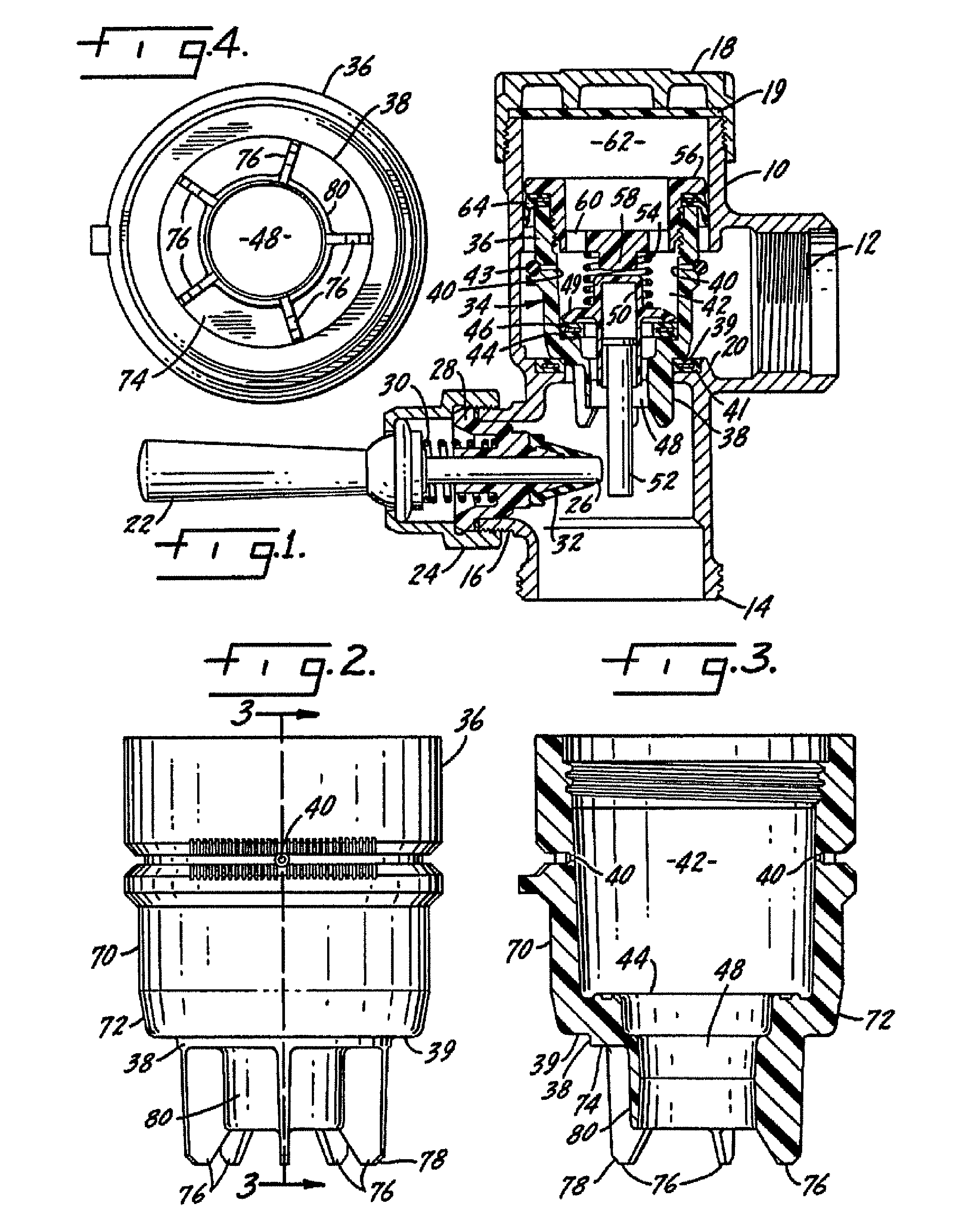
[0014] The piston of the present invention is conventionally used with flushometer assemblies for urinals or water closets. The flushometer piston is designed to control the flow of water through the flushometer to provide a specific quantity of water for each flushing operation, with the water passing through the flushometer at a high flow rate even when the water pressure is on the low side of the range of water pressures commonly found in the United States. Although the invention will be described in which the desired volume per flush is 1.6 gallons or six liters, it should be understood that the size of the various parts may be modified to provide different volumes of water per flush.

[0015] The flushometer as shown has a generally hollow valve body 10 which includes an inlet connection 12, an outlet connection 14, and a handle coupling connection 16. The top of the valve body is closed by a cover 18 and there may be a seal element 19 between the cover and the body. A main valve...


PUM


Abstract

A flushometer for use with urinals or water closets includes a hollow valve body having an inlet, an outlet, and a valve seat therebetween. There is a piston or diaphragm movable in the hollow valve body to a closing position on the valve seat to control flow through the valve. A pressure chamber is above the piston or diaphragm for holding it on the valve seat. The piston or diaphragm includes a plurality of bypass orifices to connect the inlet with the pressure chamber to provide fluid to move the piston or diaphragm to the closing position.

Description

BACKGROUND OF THE INVENTION [0001] This invention generally relates to a diaphragm or piston-type flushometer for use in a urinal, water closet, or the like. More particularly, the invention relates to a flushometer having a plurality of bypass orifices. [0002] Piston-type flushometers having bypass orifices are well known, as exemplified by the flush valve shown in U.S. Pat. No. 4,261,545, which is hereby incorporated herein by reference. Diaphragm-type flushometers also have bypass orifices, as exemplified by the flush valve shown in U.S. Pat. No. 6,616,119, which is hereby incorporated herein by reference. The bypass orifice provides inlet fluid pressure above the piston or diaphragm for closing and then holding the piston assembly or diaphragm on the valve seat after the flush operation. The orifice is sized to allow a predetermined amount of fluid flow through the flush valve before the valve closes. [0003] In order for the flush valve to work properly, the bypass orifice must ...

Claims


Application Information

Patent Timeline
IPC IPC(8): F16K31/12
CPCF16K31/3835E03D3/04
Inventor CARROLL, DANIELSCHMITT, PAUL
Owner SLOAN VALVE COMPANY
Why Eureka
Try Eureka