Ergonomic Center Handle Fish Tape

a center handle and tape technology, applied in the field of fish tapes, can solve the problems of requiring significant force, difficult to wind and unwind the tape, and virtually impossible to push through long conduit lengths, so as to reduce the drop strength, improve the drop strength, and rotate easily

Inactive Publication Date: 2007-11-29
ACTUANT CORP
View PDF7 Cites 12 Cited by
  • Summary
  • Abstract
  • Description
  • Claims
  • Application Information

AI Technical Summary

Benefits of technology

[0015] The cassette is preferably rotatably mounted in the cavity of the housing by a retaining ring. The retaining ring has an axially extending inner peripheral wall that is sonically welded to the inner peripheral wall of the housing, and it has a radially extending annular outer wall disposed in an annular, outward facing recess of the outer wall of the cassette so as to overlap the outer wall of the cassette without inhibiting rotation of the cassette. The cassette handle is mounted to the outer wall of the cassette to extend axially parallel to the center axis so that the cassette can be rotated easily with one hand while the housing is supported by the reel handle. The fish tape is guided along the feed direction by a passageway in the housing extending tangentially from the annular cavity to the exit aperture.
[0016] The reel handle and the housing are preferably molded of an impact modified plastic as a monolithic structure. The cassette and retaining ring are separately molded impact modified plastic components, and the fish tape is a flat metal tape. The housing and retaining ring are preferably permanently joined using a sonic welding technique. The combination of the impact plastic and the sonic welding gives a preferred version of the assembly an improved drop strength compared to other fish tape devices on the m...

Problems solved by technology

Because typical electrical wire is very flexible, pushing it through long lengths of conduit is virtually impossible.
This reel arrangement makes it somewhat difficult to wind and unwind the tape.
Given the relative rigid and springy characteristics of the fish tape, coiling the fish tape can require significant force and can be time consuming and frustrating, particularly if the tape binds inside of the reel.
While this design provides significant benefits over other conventional fish tape reels, it lack ergonomic features that make it comfortable to operate.
One common problem with conventional fish tape reels is that the handle, as in U.S. Des. Pat. No. D408,749, is ordinarily a carrying handle for transpor...

Method used


Image

  • Ergonomic Center Handle Fish Tape
  • Ergonomic Center Handle Fish Tape
  • Ergonomic Center Handle Fish Tape

Examples


Embodiment Construction

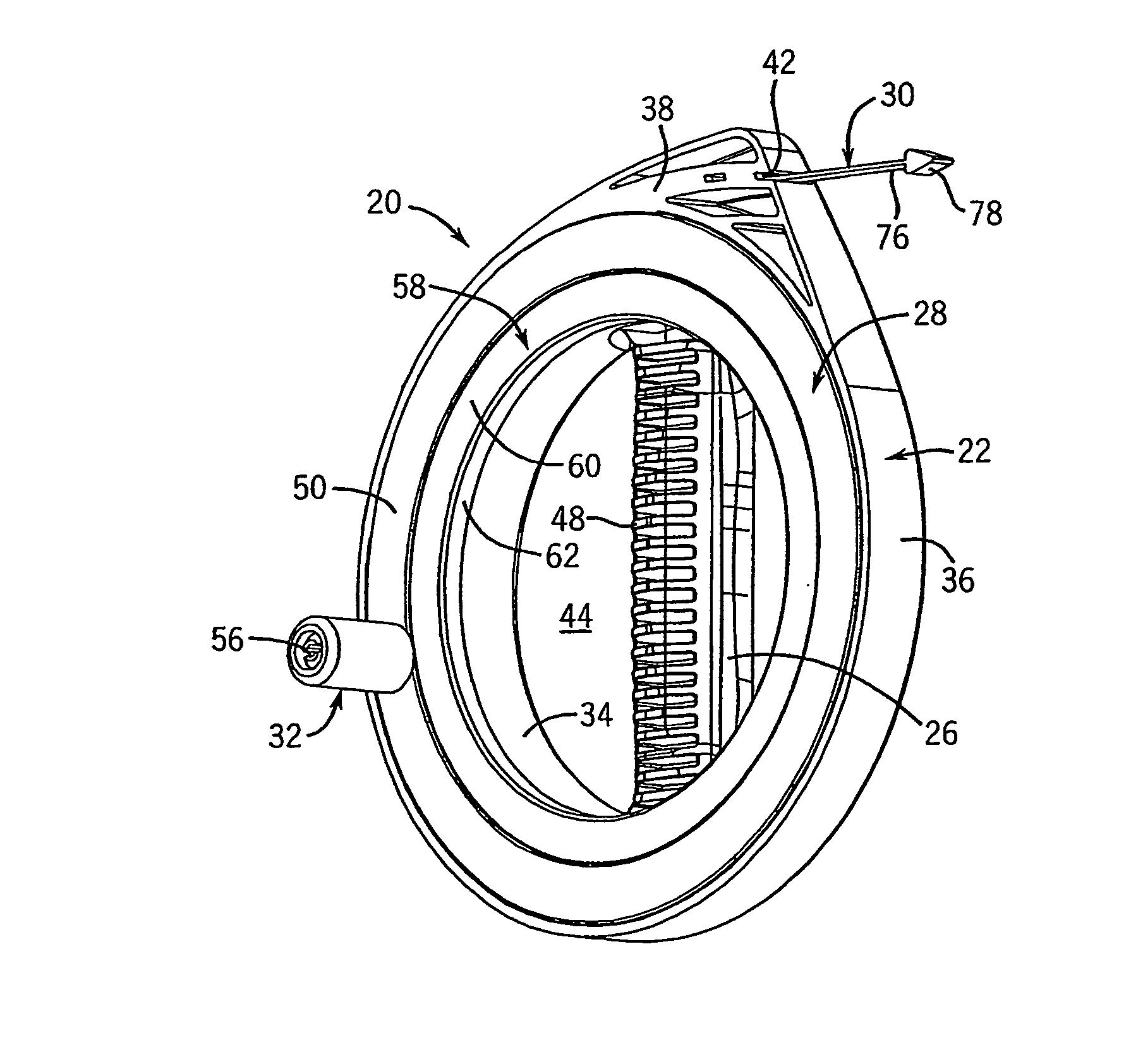
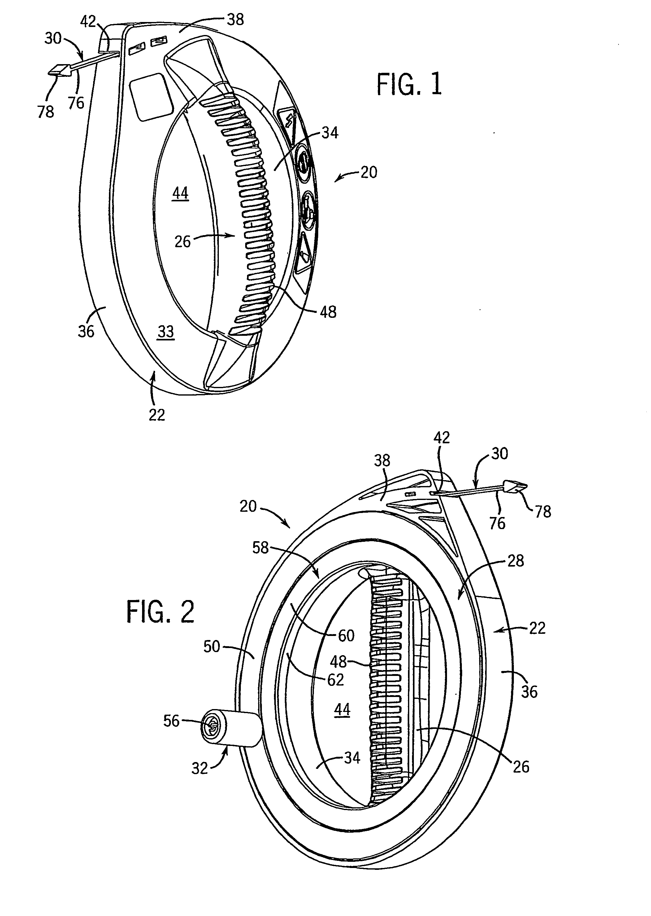
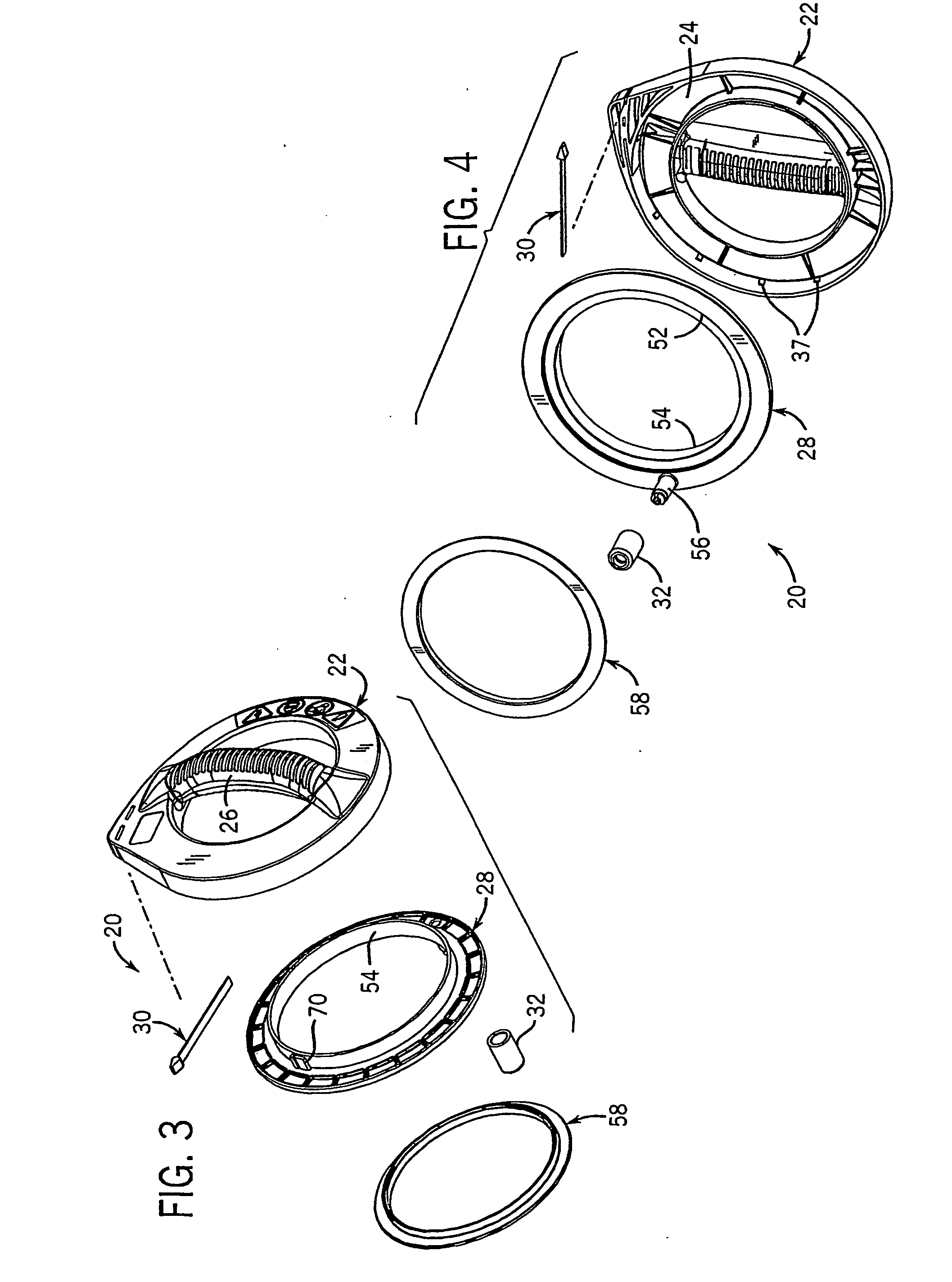
[0029] Referring to FIGS. 1-2, 5-6 and 8, a fish tape reel assembly 20 has a housing 22 with an annular cavity 24 formed therein, and an integral reel handle 26. A fish tape cassette 28 is mounted in the cavity 24 so as to be rotatable about a center axis 29. The cassette 28 contains fish tape 30 and has a cassette handle 32. A user rotates the cassette 28 to deploy or retrieve the tape 30. Preferably, the housing 22 and cassette 28 are formed from molded plastic, such as impact modified ABS, using methods known in the art, such as injection molding.

[0030] Referring now to FIGS. 3, 4 and 7, the housing 22 receives the cassette 28 in the annular cavity 24, which is defined by a generally annular, and somewhat outwardly tapering back wall 33 and inner 34 and outer 36 peripheral walls extending substantially parallel to the center axis 29. The outer peripheral wall 36 extends slightly further in the axial direction than the inner peripheral wall 34. As shown in FIGS. 4, 7 and 9, a plu...


PUM


Abstract

A fish tape reel has an ergonomic center handle disposed across the center opening of an annular, high-drop strength housing that defines a cavity containing a fish tape cassette. The interior of the cavity can have rib-like friction reducers against which the fish tape slides. Flat metal fish tape is wound around a hub of the cassette with one end secured to the cassette and the opposite end fed through an exit aperture of the housing. The cassette is rotatably mounted in the housing cavity by a retaining ring sonically welded to the housing. A handle mounted to the cassette facilitates rotating the cassette relative to the housing for winding and unwinding the fish tape. The ergonomic handle is positioned generally along a vertically center line of the housing in position for grasping with a straight wrist when winding and unwinding the fish tape.

Description

CROSS-REFERENCE TO RELATED APPLICATION [0001] This application claims benefit to U.S. provisional application Ser. No. 60 / 493,670, filed Aug. 8, 2003.STATEMENT OF FEDERALLY SPONSORED RESEARCH OR DEVELOPMENT [0002] Not applicable. BACKGROUND OF THE INVENTION [0003] 1. Technical Field [0004] The present invention relates to fish tapes of the type used by electricians to pull wire through conduit or other spaces, and more particularly to the fish tape reel assembly. [0005] 2. Description of the Related Art [0006] A fish tape is a stiff but bendable wire, flexible rod or flat tape typically used to install wire in conduit, through existing walls, under carpet, over dropped ceilings, or through other tight spaces. Because typical electrical wire is very flexible, pushing it through long lengths of conduit is virtually impossible. Pulling wire along the desired path is much more effective. In order to pull the wire, a fish tape, being more rigid than electrical wire, is first pushed along...

Claims


Application Information

Patent Timeline
IPC IPC(8): H02G1/08B65HB65H57/28B65H75/40
CPCB65H75/406B65H2701/376B65H2402/412
Inventor ZIEBART, BERNARD J.HUEBSCHEN, DAVID A.
Owner ACTUANT CORP
Why Eureka
Try Eureka