Load control mechanism for self-propelled working machine

a self-propelled working machine and load control technology, which is applied in the direction of machines/engines, electric generator control, motor propulsion transmission, etc., can solve the problems of operator's work burden increasing, the finish of the work deteriorating, and the inability to perform the work at the optimal output, so as to achieve the maximum working output. the effect of easy and quick calculation

Active Publication Date: 2007-11-29
HONDA MOTOR CO LTD
View PDF6 Cites 28 Cited by
  • Summary
  • Abstract
  • Description
  • Claims
  • Application Information

AI Technical Summary

Benefits of technology

[0017]According to the load control mechanism, the no-load output characteristic, which is a relationship between engine rotational speed and no-load output during no-load driving, and the working output characteristic, which is a relationship bet

Problems solved by technology

In such self-propelled working machines that perform work by using an internal combustion engine, if working conditions are bad and working load is too large, it is not possible to perform the work at optimum output and the finish of the work deterio

Method used


Image

  • Load control mechanism for self-propelled working machine
  • Load control mechanism for self-propelled working machine
  • Load control mechanism for self-propelled working machine

Examples


Embodiment Construction

[0032]An embodiment according to the invention will be described below with reference to FIGS. 1 to 12.

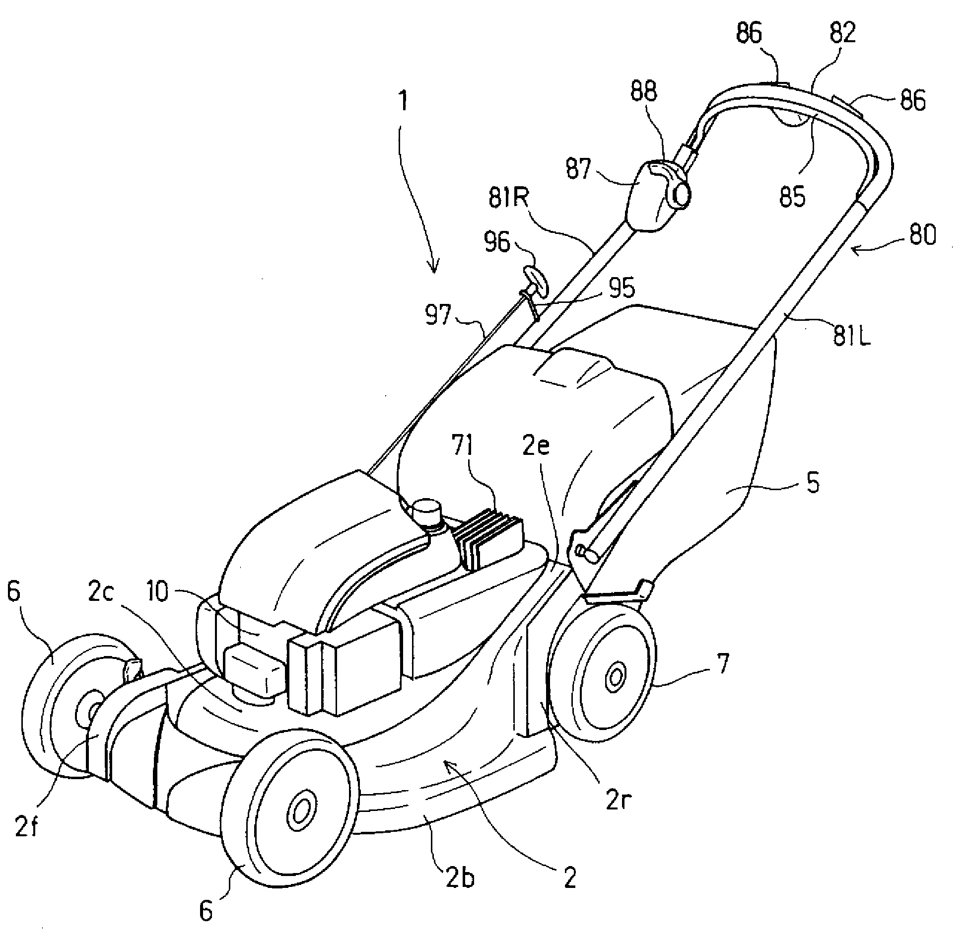
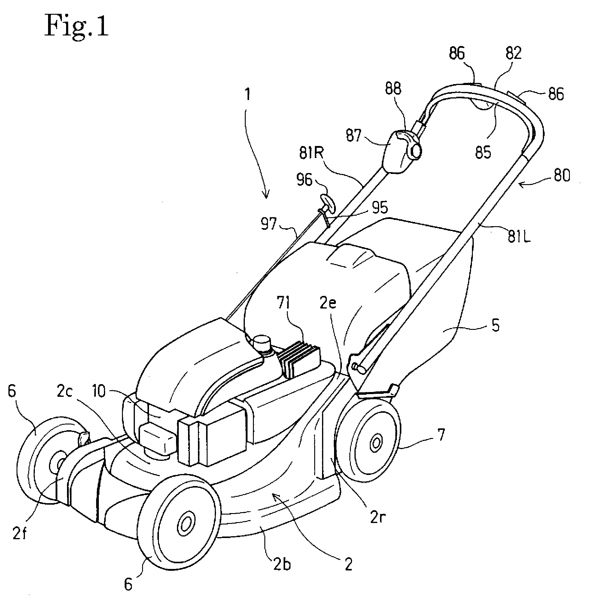
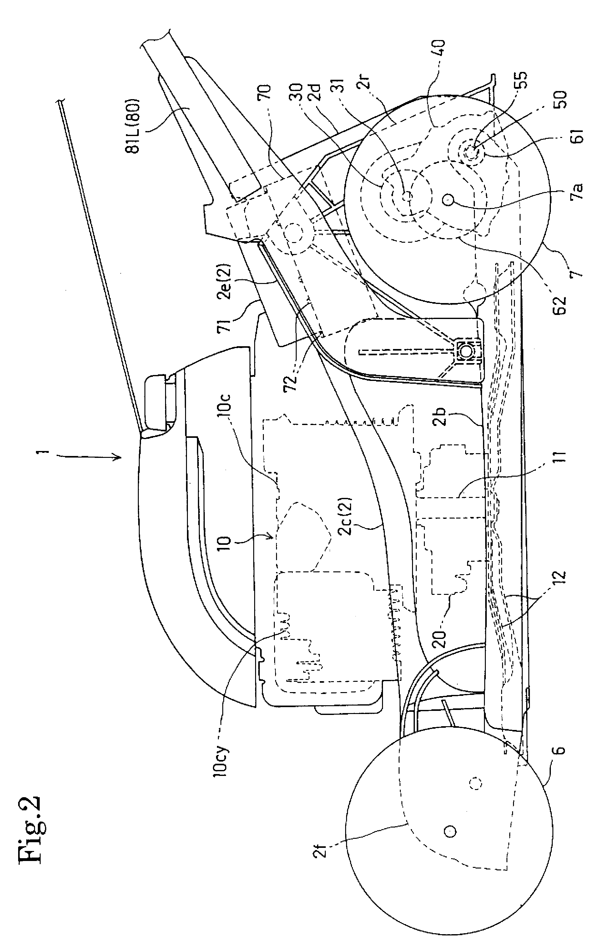
[0033]A lawn mower 1 according to this embodiment is a hybrid self-propelled lawn mower that can rotate mowing blades 12 (see FIG. 2) by a four-stroke cycle internal combustion engine 10 to perform a mowing operation and can self-travel by a travel DC motor 30.

[0034]FIG. 1 shows a perspective view showing the entire lawn mower 1, FIG. 2 shows a side view of a body of the lawn mower, FIG. 3 is a plan view of the body of the lawn mower, and FIG. 4 is a rear view of the body of the lawn mower.

[0035]Referring to FIG. 1, a blade housing 2, which supports the mowing blades 12 (see FIG. 2) rotating above the ground and covers the blades from above, is supported by a pair of (left and right) front wheels 6 and 6 and rear wheels 7 and 7 so as to freely travel on the ground.

[0036]A direction in which the lawn mower 1 moves forward will be referred as a forward direction in the description, a...


PUM


Abstract

A self-propelled working machine, which performs work by using power of an internal combustion engine 10 and travels by using power of an electric motor 30, includes a mechanical governor 75 for maintaining the engine at a designated engine rotational speed Nf. A load control mechanism for the working machine has a maximum working output calculator that calculates a maximum working output Qf from the designated engine rotational speed, an actual working load calculator that calculates an actual working load Qr from the designated engine rotational speed Nf and a detected actual engine rotational speed Nr, and a limit speed calculator that calculates a limit speed Vc from the maximum working output Qf and the actual working load Qr. A travel controller operates and controls the electric motor 30 by setting a travel speed V to the limit speed Vc when the actual engine rotational speed Nr is decreased to be lower than the designated engine rotational speed Nf. The travel speed of the working machine is automatically controlled so that the working load is calculated from the driving condition of the internal combustion engine to ensure the working load to be appropriate. Thus excellent finish of the working is maintained and the operator is relieved from burden.

Description

BACKGROUND OF THE INVENTION[0001]1. Field of the Invention[0002]The present invention relates to a self-propelled working machine, such as a lawn mower, that performs work by using power of an internal combustion engine and travels by using power of an electric motor, and more particularly, to a self-propelled working machine of which travel is controlled in response to working load.[0003]2. Description of the Related Art[0004]In self-propelled working machines, in general, working load increases when travel speed is high during the working, and working load decreases when travel speed is low.[0005]In such self-propelled working machines that perform work by using an internal combustion engine, if working conditions are bad and working load is too large, it is not possible to perform the work at optimum output and the finish of the work deteriorates, or engine stall occurs. For this reason, the operator determines the degree of the working load by hearing working sounds or observing...

Claims


Application Information

Patent Timeline
IPC IPC(8): B60L11/12A01D75/18H02P9/04F02D41/00F02D31/00B60L50/10B60L50/15
CPCA01D2034/6843A01D2101/00B60K6/46B60W10/06B60W10/08B60W20/00A01D69/02Y02T10/6217Y02T10/6286Y02T10/7258A01D34/006A01D34/69B60Y2200/225B60L50/00Y02T10/62Y02T10/72F02N11/00
Inventor KAWAKAMI, TOSHIAKIKOBAYASHI, HIROSHI
Owner HONDA MOTOR CO LTD
Why Eureka
Try Eureka