

Switch circuit
a switch circuit and circuit technology, applied in the field of switch circuits, can solve the problems of loss generated in the branch path in off, hard to achieve enough characteristics in the millimeter wave band, and improve so as to achieve the effect of improving the characteristics of the switch circui
- Summary
- Abstract
- Description
- Claims
- Application Information
AI Technical Summary
Benefits of technology
Problems solved by technology
Method used
Image


Examples
first embodiment
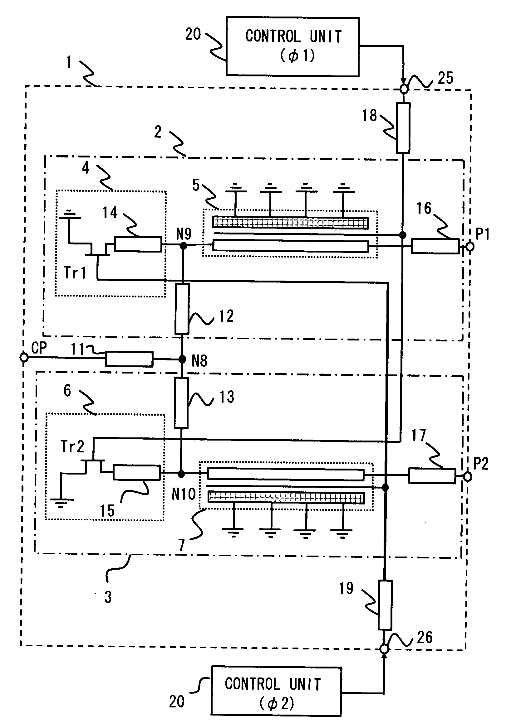
[0023]FIG. 1 is a configuration diagram showing an overall switch circuit according to an embodiment of the present invention.
[0024]As shown in FIG. 1, a switch circuit 1 is a SPDT (Single Pole Double-Throw) type switch circuit. The switch circuit 1 includes a common input terminal CP and two output terminals (first output terminal P1 and second output terminal P2).
[0025]A signal input from the input terminal CP according to a control signal from a control unit 20 is transmitted to either of the output terminal P1 or output terminal P2. Note that the switch circuit 1 is formed over a GaAs substrate having approximately 40 μm thickness.
[0026]The switch circuit 1 includes a branch path 2 (first branch path) and branch path 3 (second branch path). The branch path 2 and branch path 3 are connected in parallel to a node N8 (diverging point). By making either of the branch path 2 or branch path 3 to be in OFF state and another to be in ON state, an input signal from the input terminal CP ...
second embodiment
[0041]A second embodiment of the present invention is described hereinafter in detail with reference to FIG. 5. In the following descriptions, like parts are marked same number, and repeated explanations are omitted.
[0042]A difference from the first embodiment is that winding inductors 140 and 150 are employed instead of the transmission lines 14 and 15. The winding inductor 140 (winding inductor 150) enables to deal with a case in which a value of inductor of the transmission line is not enough. Specifically in a low operating frequency, inductor included in the transmission line 14 is sometimes not enough in low operating frequency band. To compensate this, winding inductors that are able to obtain enough inductor value are employed. In this example, winding inductors of 145 pH are employed at an operating frequency of 38 GHz.
[0043]The components included in the switch circuit 100 can be configured as follows for example. Note that each transmission line in this embodiment is cons...
third embodiment
[0044]A third embodiment of the present invention is described hereinafter in detail with reference to FIGS. 6, 7 and 8. In the following descriptions, like parts are marked same number, and repeated explanations are omitted.
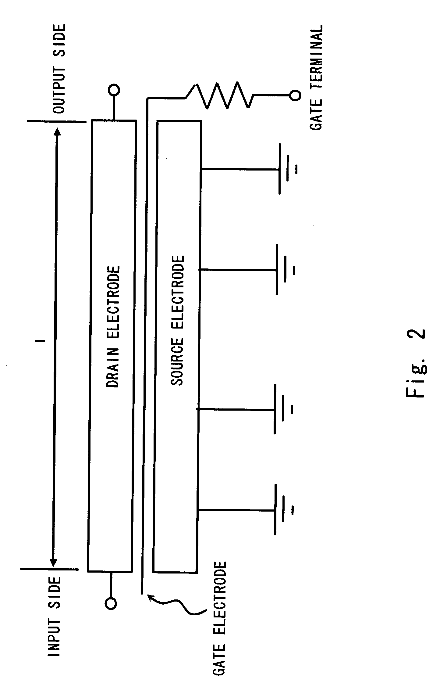
[0045]Differences are that distributed constant lines 50 and 70 having diode structure are employed instead of the distributed constant lines 5 and 7 having FET structure, and diodes D1 and D2 are employed instead of field effect transistors Tr1 and Tr2. Further as shown in FIG. 6, a connection path for a control signal input from the control unit 20 to each of the branch paths is also modified.
[0046]The distributed constant line 50 controls ON or OFF state of the branch path 2. The distributed constant line 50 has a diode structure. The diode structure included in the distributed constant line 50 is a schottky diode structure having a substrate and wiring region as shown in FIG. 7. In this embodiment, the substrate region is formed by an ohmic electrode and the...
PUM
 Abstract
Description
Claims
Application Information