
Touch screen system and display device using the same

a technology of touch screen and display device, which is applied in the direction of static indicating device, mechanical pattern conversion, instruments, etc., can solve the problems of increasing manufacturing cost, connection failure, and inability to achieve thin profile and light weight of lcd device, and achieve thin profile and light weight devi

Inactive Publication Date: 2007-11-29
LG DISPLAY CO LTD
View PDF13 Cites 10 Cited by
  • Summary
  • Abstract
  • Description
  • Claims
  • Application Information

AI Technical Summary

Benefits of technology

[0016] An object of the present invention is to provide a touch screen system having a signal connection structure between a touch panel and a touch controller for obtaining a thin profile and light weight device.
[0017] Another object of the present invention is to provide a display device having a touch screen system having a signal connection structure between a touch panel and a touch controller for obtaining a thin profile and light weight device.

Problems solved by technology

Thus, obtaining a thin profile and light weight of the LCD device is not achieved.
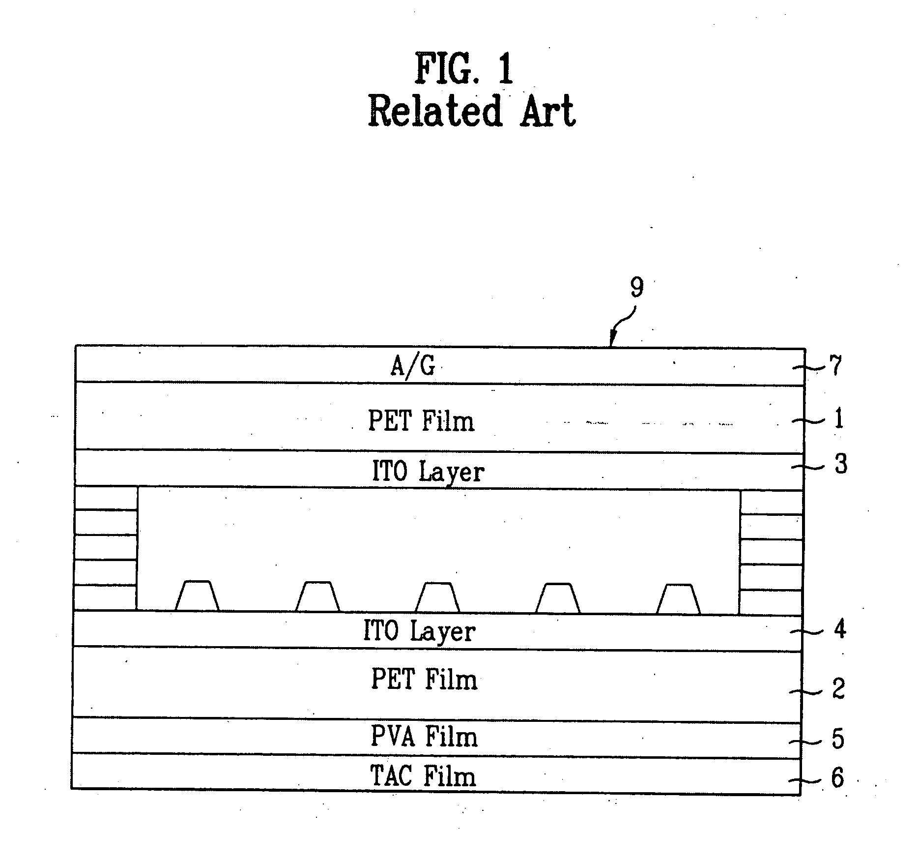
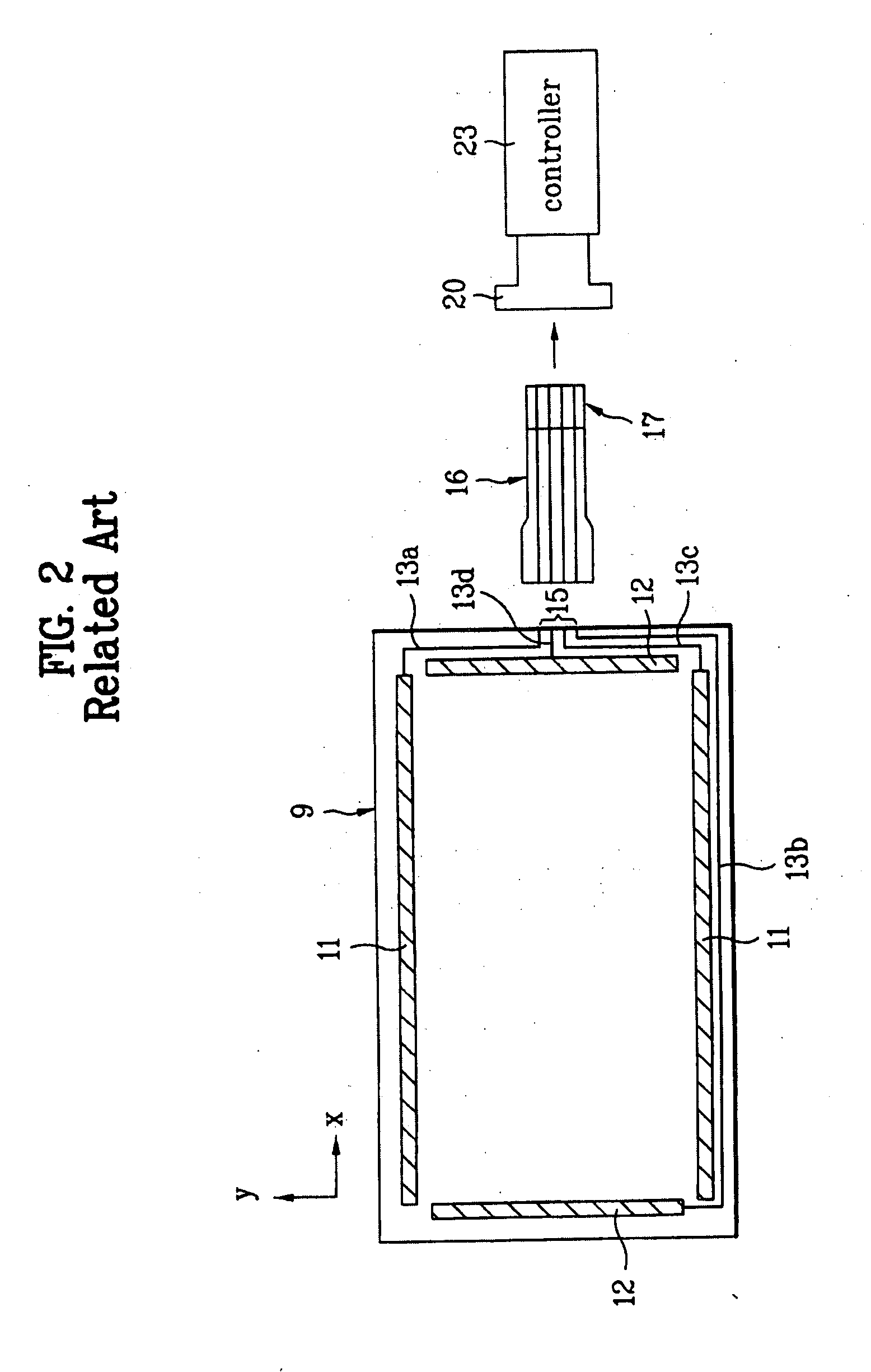
Second, in order to connect the FPCB 16 of the touch panel 9 to the touch controller 23, the FPCB connector 20 is required, thereby increasing manufacturing costs.
Third, when connecting the signal lines of the FPCB 16 to the FPCB connector 20, a connection failure may be generated.

Method used


Image

  • Touch screen system and display device using the same
  • Touch screen system and display device using the same
  • Touch screen system and display device using the same

Examples


Embodiment Construction

[0038] Reference will now be made in detail to the preferred embodiments of the present invention, examples of which are illustrated in the accompanying drawings.

[0039] A touch screen assembly according to the present invention will be described with reference to the accompanying drawings.

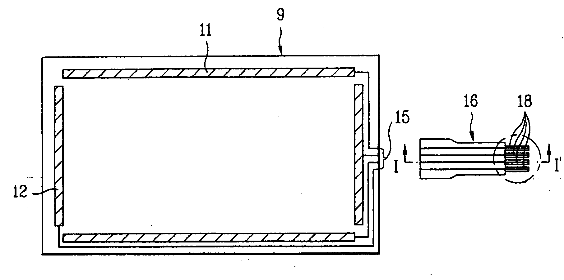
[0040]FIG. 3 is a plan view of an exemplary signal connection structure between an extension and controller connection part according to the present invention. In FIG. 3, a plurality of connection pads 22 of a touch controller 23 may be formed on a PCB substrate having the touch controller 23 contained therein, and an anisotropic conductive film (ACF) 25 may be formed on an upper surface of the connection pads 22. In addition, an extension 16 may be provided to be connected to a touch panel, which may be similar to the touch panel 9 (of FIG. 2), and may be formed on the ACF 25. Accordingly, a plurality of signal lines 18 formed on the extension 16 may be connected to the connection pads 22. Thus,...


PUM

PropertyMeasurementUnit
conductiveaaaaaaaaaa
anisotropic conductiveaaaaaaaaaa
widthaaaaaaaaaa

Abstract

A touch screen system includes a touch panel to input image signals, a touch controller to drive the touch panel, an extension between the touch panel and the touch controller, and an anisotropic conductive film electrically interconnecting the extension to the touch controller.

Description

[0001] The present invention claims the benefit of Korean Patent Application Nos. P2002-71681 and P2002-72353 filed in Korea on Nov. 18, 2002 and Nov. 20, 2002, respectively, which are hereby incorporated by reference. BACKGROUND OF THE INVENTION [0002] 1. Field of the Invention [0003] The present invention relates to a touch panel system, and more particularly, to a touch panel system for a liquid crystal display (LCD) device. [0004] 2. Discussion of the Related Art [0005] Presently, liquid crystal display (LCD) devices are commonly used because of their ability to produce high quality images, as well as their thin profile, light weight, and low power consumption. Liquid crystal module (LCM) devices are used for displaying video signals input from external sources, such as LCD panels, and commonly include polarizing plates, power sources, such as backlight devices, and light-guiding plates. The LCD panels include upper and lower glass substrates, and liquid crystal material injecte...

Claims


Application Information

Patent Timeline
Patent Type & Authority Applications(United States)
IPC IPC(8): G06F3/041G02F1/13G06F3/048G06K11/06G09G5/00
CPCG06F3/045G06F3/0488H05K3/323H05K2201/10992H05K3/403H05K2201/09172H05K3/361
Inventor HONG, HEE JUNG
Owner LG DISPLAY CO LTD
Learn More