

Calibration code strip with permutative grey scale calibration pattern
a calibration pattern and calibration code technology, applied in the field of medical devices, can solve the problems of inconvenient user experience, time-consuming manual input or selection of calibration codes, and inaccurate and/or inaccurate determination of analy
- Summary
- Abstract
- Description
- Claims
- Application Information
AI Technical Summary
Problems solved by technology
Method used
Image

Examples
Embodiment Construction
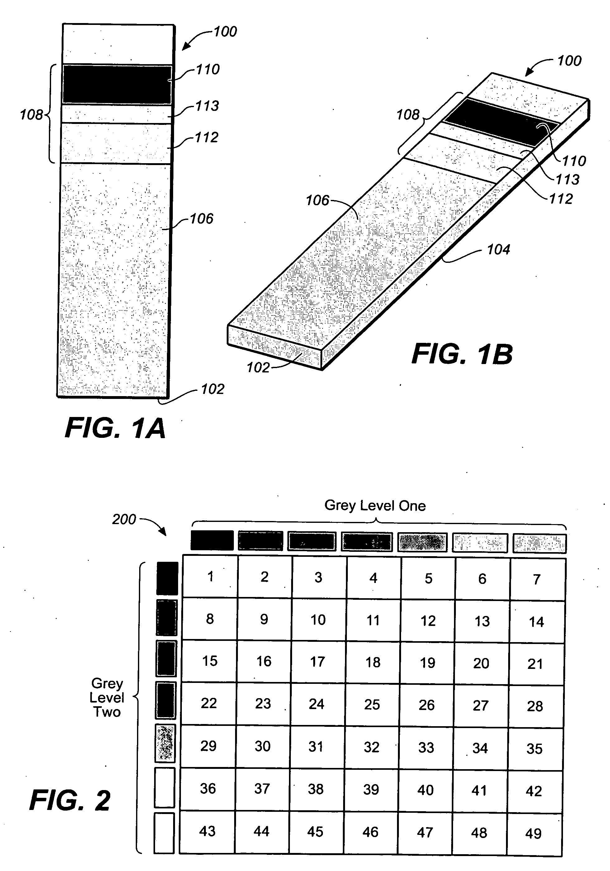
[0019]FIGS. 1A and 1B are simplified bottom and perspective views respectively of a test strip 100 for the determination of an analyte (such as glucose) in a body fluid sample (e.g. a whole blood sample) according to an exemplary embodiment of the present invention. Test strip 100 includes a substrate 102 with a working surface 104 (not visible in the perspective of FIGS. 1A and 1B) for receiving the body fluid sample and a reverse surface 106 in opposition to working surface 104.
[0020]Test strip 100 also includes a permutative grey scale calibration pattern 108 disposed on reverse surface 106. In the embodiment of FIGS. 1A and 1B, the permutative grey scale calibration pattern 108 includes a first grey scale region 110 and a second grey scale region 112, with the first and second grey scale regions 110 and 112, respectively, being spaced apart by gap 113. However, once apprised of the present disclosure, one skilled in the art will recognize that grey scale calibration patterns emp...
PUM
 Abstract
Description
Claims
Application Information