Supercharge Your Innovation With Domain-Expert AI Agents!

Light Guide Lens and Light Emitting Diode Package Structure having the Light Guide Lens

a technology of light guide lens and light emitting diode, which is applied in the direction of lighting and heating apparatus, lighting device details, instruments, etc., can solve the problems of lcd whose uniform illumination-providing surface source is fabricated at the cost of a thickened backlight module, is necessarily bulky, and has a short life, so as to prevent hot spots and minimize the loss of light energy. , the effect of reducing the loss of light energy

Active Publication Date: 2007-11-29
IND TECH RES INST
View PDF5 Cites 21 Cited by
  • Summary
  • Abstract
  • Description
  • Claims
  • Application Information

AI Technical Summary

Benefits of technology

The present invention provides a light guide lens that allows incident light to exit in a lateral manner, making it easier to assemble and reducing manufacturing costs. The lens has a simple structure with refraction and reflection structures, and a light emission surface with planes that allow light to penetrate and leave the lens body. The refraction structures refract the incident light in a way that the parallel light rays turn into reflected light rays, which then exit the lens body. The light guide lens is made of a resin or transparent polymer and can be used in a light emitting diode package structure. Overall, the present invention provides a more efficient and cost-effective solution for achieving uniform illumination.

Problems solved by technology

Cold cathode fluorescent lamps, however, contain mercury, consume too much power and have short lifetime.
However, an LED is a point source and thereby is unlikely to provide uniform illumination for a light emission surface of a backlight module, and in consequence granular hot spots are visible in front of the backlight module.
Inasmuch as the appeal of LCDs lies in the compactness thereof, an LCD whose uniform illumination-providing surface source is fabricated at the cost of a thickened backlight module is necessarily bulky and thereby is hardly in line with the trend of LCD products.
However, the serrate outer surface 11 can only direct incoming light rays at a rough target, and thus it is not true that light rays coming in any direction necessarily exit laterally.
In particular, light rays emitted in the direction of the top of the light emitting diode 2 inevitably bring about a hot spot.
Hence, in practice, the lens cap 1 is superimposed by a transparent panel having an affixed reflective sheet configured to hide the hot spot from view, thus resulting in a complicated, high-cost assembly process.
The serrate structure of the outer surface 11 of the lens cap 1 is so complicated that it has to be fabricated by means of a combination of dies, thus increasing production costs.

Method used


Image

  • Light Guide Lens and Light Emitting Diode Package Structure having the Light Guide Lens
  • Light Guide Lens and Light Emitting Diode Package Structure having the Light Guide Lens
  • Light Guide Lens and Light Emitting Diode Package Structure having the Light Guide Lens

Examples


Embodiment Construction

[0028]The present invention is herein illustrated with specific embodiments, so that one skilled in the pertinent art can easily understand other advantages and effects of the present invention from the disclosure of the invention.

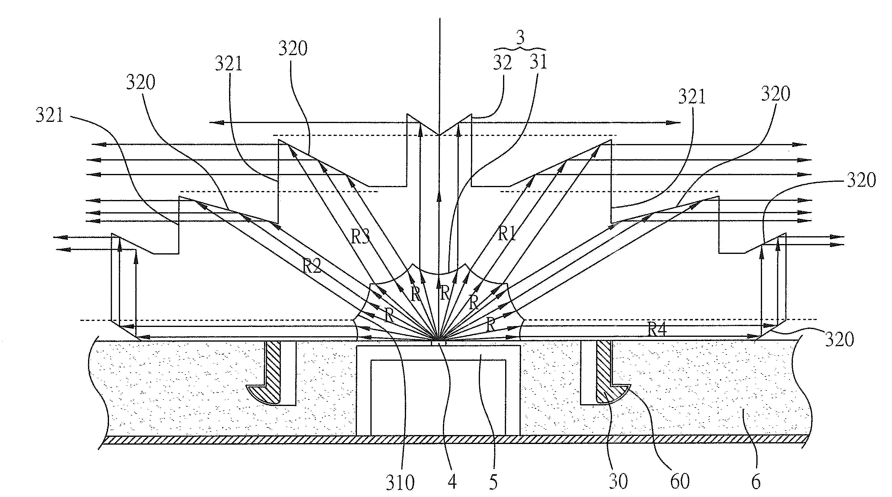
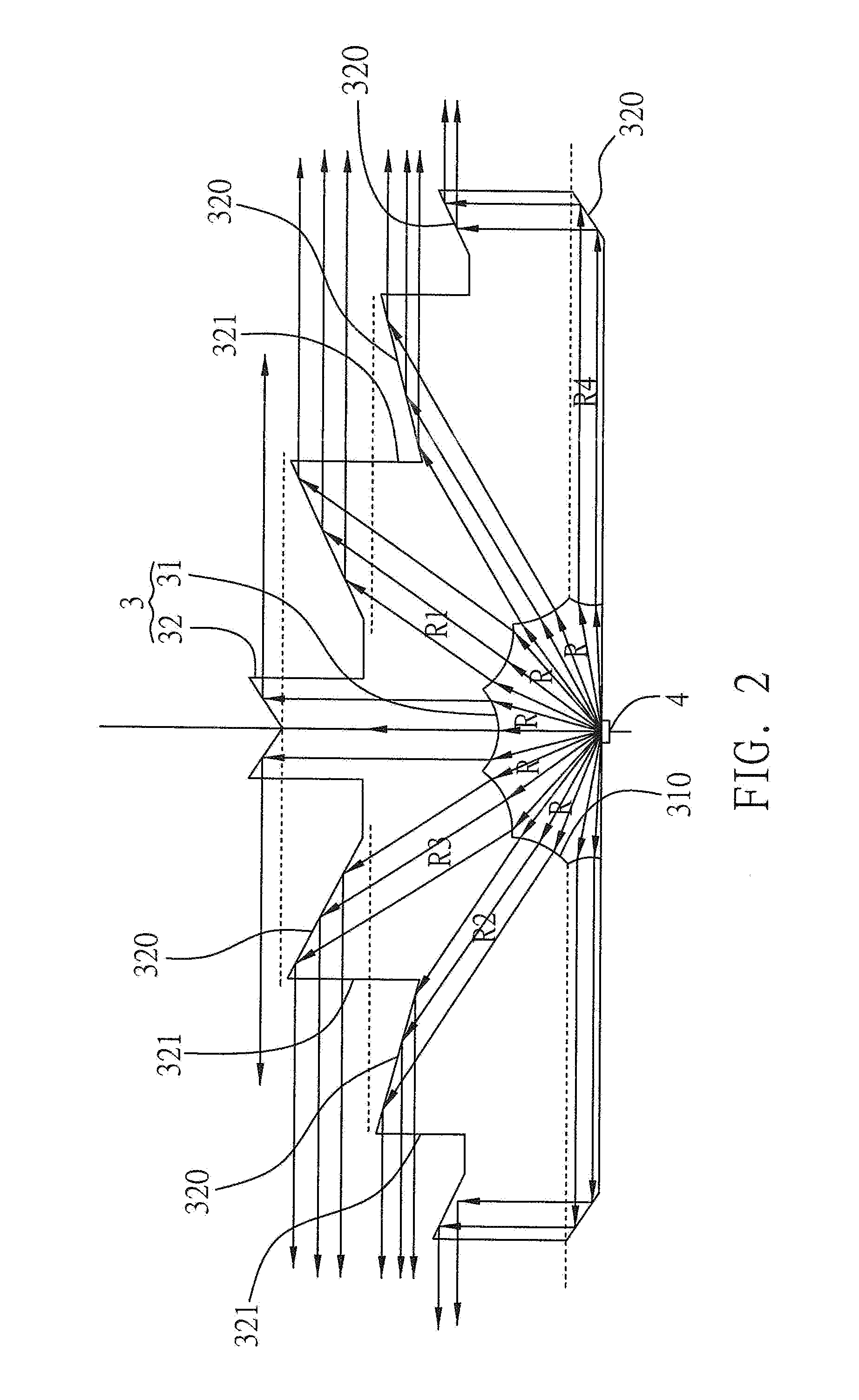
[0029]Referring to FIG. 2 which is a schematic view of a preferred embodiment of a light guide lens in accordance with the present invention, the light guide lens turns incident light rays R coming in all directions into laterally exiting light rays R. The light guide lens comprises a lens body 3, a plurality of refraction structures 310, and a plurality of reflection structures 320. The lens body 3 further comprises a light incidence surface 31 for receiving incident light rays R and a light emission surface 32 for emitting outgoing light rays R. The lens body 3 is made of one of a resin and a transparent polymer. The plurality of refraction structures 310 are formed on the light incidence surface 31 and configured to refract incident light rays R such th...


PUM


Abstract

A light guide lens includes a lens body having a light incidence surface and a light emission surface, a plurality of refraction structures formed on the light incidence surface, and a plurality of reflection structures formed on the light emission surface. The refraction structures send incoming light rays to the light emission surface by refraction. Each of the refraction structures turns incoming light rays coming in all directions into refracted parallel light rays. The refracted parallel light rays arriving from the refraction structures reflect off the corresponding reflection structures and then laterally exit the lens body. The refracted parallel light rays arriving from each of the refraction structures travel to a corresponding one of the reflection structures, such that eventually the incoming light rays exit laterally. The present invention further provides a light emitting diode package structure having the light guide lens.

Description

BACKGROUND OF THE INVENTION[0001]1. Field of the Invention[0002]The present invention relates to light guide lenses and light emitting diode (LED) package structures, and more particularly, to a light guide lens and a light emitting diode (LED) package structure for turning incident LED light coming in all directions into laterally exiting light.[0003]2. Description of the Prior Art[0004]Backlight modules of conventional liquid crystal displays use mostly cold cathode fluorescent lamps (CCFLs) as light sources. Cold cathode fluorescent lamps, however, contain mercury, consume too much power and have short lifetime. Hence, the current trend is toward replacing cold cathode fluorescent lamps by light emitting diodes (hereinafter referred to as LEDs) when designing the light sources of backlight modules. LEDs are durable and contamination-free. Red, green, blue monochromatic LEDs have advantages, such as a single wavelength and a wide color gamut, and thus resultant liquid crystal disp...

Claims


Application Information

Patent Timeline
Patent Type & Authority Applications(United States)
IPC IPC(8): G02B17/00
CPCG02B19/0071G02B19/0061G02B19/0028
Inventor PAO, YU-NANYAO, PO-HUNGLIN, TSUNG-HSIN
Owner IND TECH RES INST
Features
  • R&D
  • Intellectual Property
  • Life Sciences
  • Materials
  • Tech Scout
  • Unparalleled Data Quality
  • Higher Quality Content
  • 60% Fewer Hallucinations
Learn More