Backlight module and light guide plate thereof

a backlight module and light guide plate technology, applied in the field of backlight modules, can solve the problems of low repeatability of light scattering pattern on different light guide plates, complicated fabrication process, and low and achieve the effect of improving the light utilization efficiency of backlight modules and luminous efficiency of light guide plates

Inactive Publication Date: 2007-11-29
WINTEK CORP
View PDF7 Cites 22 Cited by
  • Summary
  • Abstract
  • Description
  • Claims
  • Application Information

AI Technical Summary

Benefits of technology

[0011]Through the design of the invention, since the inclination angle of the first inner surface facing the light source is set as no more than 35 degrees, the light beams reflected by the first inner surface are directed out of the light guide plate at an angle of more than 20 degrees with respect to the normal of the light-reflecting surfa...

Problems solved by technology

However, defects on an etched steel substrate often occur to lower the repeatability of the light scattering pattern on different light guide plates.
Further, an isotropic etching process proceeding with equal velocities in all directions is hardly to avoid the formation of enlarged etch holes and fails to control the inclination surface angle of each microstructure to result in an unsatisfied luminous efficiency of a light guide plate.
Though such method may achieve a better luminous efficiency, its fabrication process is complicated because of the great...

Method used


Image

  • Backlight module and light guide plate thereof
  • Backlight module and light guide plate thereof
  • Backlight module and light guide plate thereof

Examples


Embodiment Construction

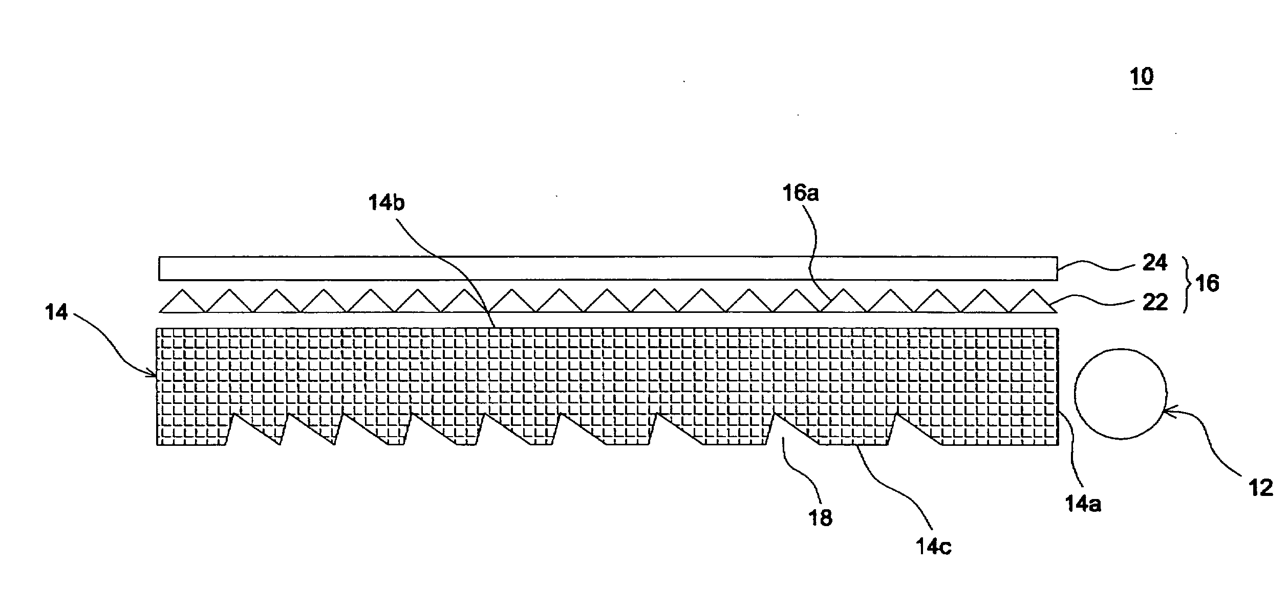
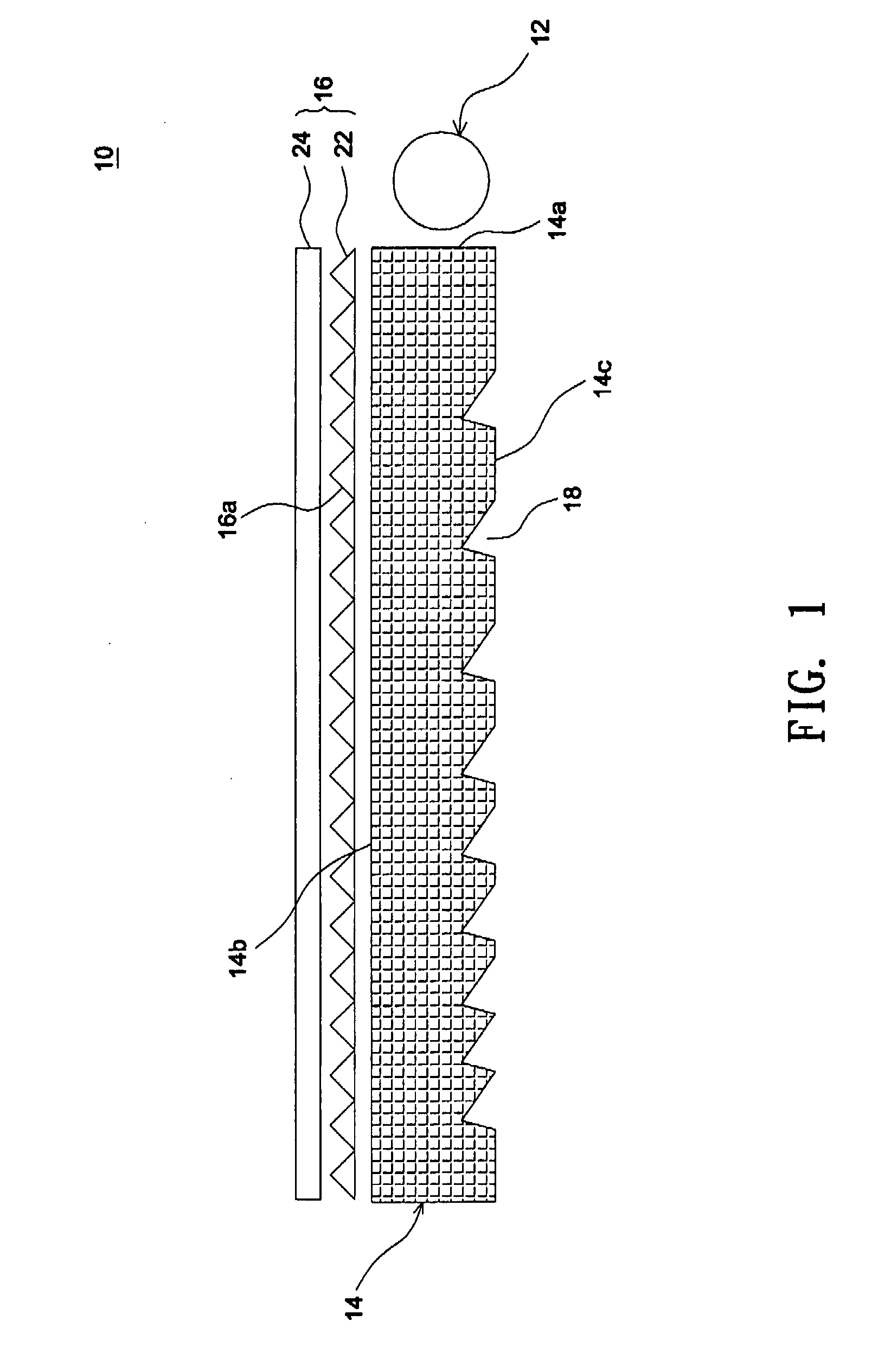
[0021]FIG. 1 shows a backlight module 10 according to an embodiment of the invention. Referring to FIG. 1, the backlight module 10 includes a light source 12, a light guide plate 14, and a brightness enhancement film (BEF) 16. The light guide plate 14 has a light-receiving surface 14a positioned next to the light source 12, a light-emitting surface 14b perpendicular to the light-receiving surface 14a, and a light-reflecting surface 14c opposite to the light-emitting surface 14b. A plurality of notches 18 are formed on the light-reflecting surface 14c and concave to the light-emitting surface 14b. The emitting light of the light source 12 are deflected by the notches 18 and then guided to a display panel (not shown) through the light-emitting surface 14b. In this embodiment, the brightness enhancement film 16 includes a dual prism structure comprised of a first prism sheet 22 and a second prism sheet 24. After light transmitted via the light-emitting surface 14b arrives at the bright...


PUM


Abstract

A backlight module includes a light source and a light guide plate. The light guide plate includes a light-receiving surface next to a light source, a light-emitting surface, and a light-reflecting surface oppose to the light-emitting surface. A plurality of notches are formed on the light-reflecting surface, and each notch has a first inner surface facing the light source and a second inner surface back to the light source and opposite to the first inner surface. The inclination angle of the first inner surface with respect to the light-reflecting surface is no more than 35 degrees.

Description

BACKGROUND OF THE INVENTION[0001](a) Field of the Invention[0002]The invention relates to a backlight module having improved light utilization efficiency and a light guide plate used in the backlight module.[0003](b) Description of the Related Art[0004]Nowadays, various well-known methods have been used to form a light guide plate with microstructures (light scattering pattern). For example, an isotropic etching process is performed on a steel plate to produce a stamper having a micro-dot pattern. However, defects on an etched steel substrate often occur to lower the repeatability of the light scattering pattern on different light guide plates. Further, an isotropic etching process proceeding with equal velocities in all directions is hardly to avoid the formation of enlarged etch holes and fails to control the inclination surface angle of each microstructure to result in an unsatisfied luminous efficiency of a light guide plate.[0005]Hence, another design where a machining tool is ...

Claims


Application Information

Patent Timeline
IPC IPC(8): F21V7/04
CPCG02B6/0036G02B6/0038G02B6/0068G02B6/0053G02B6/0051
Inventor CHEN, PING-YENGHUANG, KUO-JUICHANG, PEI-YIN
Owner WINTEK CORP
Why Eureka
Try Eureka