
Method and system for chapter marker and title boundary insertion in dv video

a technology of title boundary and insertion method, which is applied in the field of obtaining data recording, can solve the problems of large number of separate files originating from a single recording, and achieve the effect of efficient index marker insertion, and preventing too large number of index marker insertions

Inactive Publication Date: 2007-11-29
KONINKLIJKE PHILIPS ELECTRONICS NV
View PDF4 Cites 5 Cited by
  • Summary
  • Abstract
  • Description
  • Claims
  • Application Information

AI Technical Summary

Benefits of technology

[0005] According to a first aspect of the present invention, a method according to the preamble defined above is provided, in which a new recording segment is generated when a recording time discontinuity exceeds a threshold value, the recording time discontinuity being a difference between a recording end time of a first data segment and a recording start time of a next data segment. By only starting a new data segment when the recording time discontinuity exceeds a threshold value it is possible to provide an efficient index marker insertion in a data recording, and too large a number of index marker insertions is prevented. In digital video, index markers such as chapter markers are used to indicate the start of a new data segment.
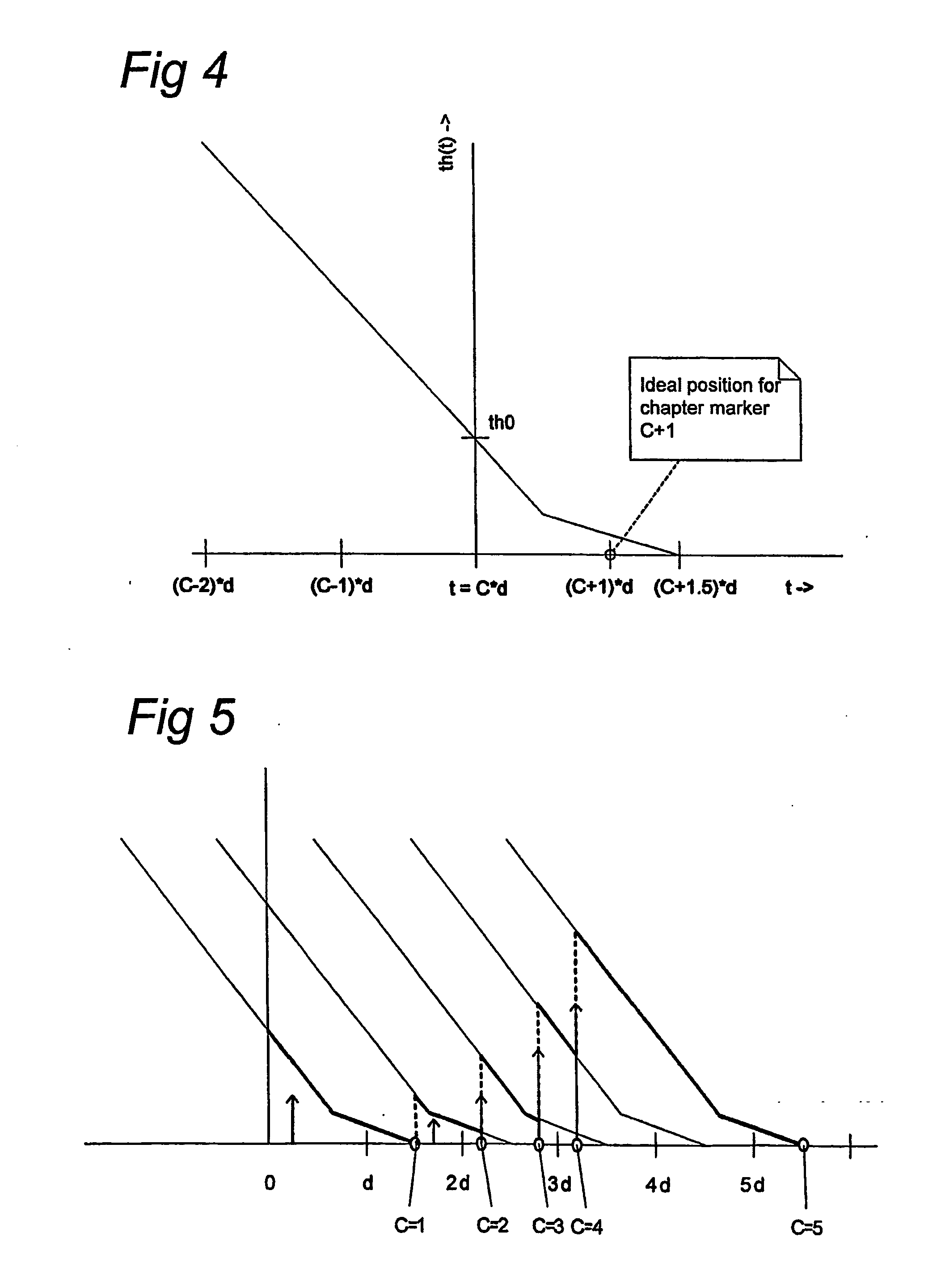
[0006] The present invention may be implemented in two manners, ‘on the fly’ and ‘pre-scan’. When using the present invention in the ‘on the fly’ embodiment, it is unknown what data is still to be recorded (time of recording, number of scene changes, etc.). In a further embodiment, using the ‘on the fly’ alternative, the threshold value is a function dependent on a desired recording segment duration and the present recording segment duration. By properly selecting the threshold value function, in which the threshold value is a predefined function in time, it is possible to prevent too large a number of index marker insertions, even when the properties of the data to be recorded is unknown (‘on the fly’).
[0007] In an embodiment of the present method, the new recording segment is generated by insertion of index markers of a first type in the data recording on the first medium. In digital video recording applications, the index markers of the first type are called chapter markers. Adding index markers is a simple operation in digital video processing, which does not require many resources in the data processing.
[0019] In a further embodiment of the present invention, the method further comprises translation of selected index markers of the first type into index markers of a second type, called title boundaries in digital video recording based on a predetermined set of criteria. The index markers of the second type may be recorded in the table of contents (TOC) of a DVD, thus allowing to select a title boundary in order to start a playback of that part of the data recording. Changing the index marker of the first type into an index marker of the second type is a simple and efficient operation.
[0020] In a further aspect, the present invention relates to a recording system as defined in the preamble above, in which the processing means are further arranged for generating a new recording segment generated when a recording time discontinuity exceeds a threshold value, the recording time discontinuity being a difference between a recording end time of a first data segment and a recording start time of a next data segment, in which the threshold value is a function dependent on a desired recording segment duration and the present recording segment duration. The processing means may further be arranged to execute the activities of the present method. The recording system according to the present invention provides advantages associated with the advantages described above in relation to the present method.

Problems solved by technology

This method and device have the disadvantage that every scene change will lead to the generation of a new file, which may lead to a very large number of separate files originating from a single recording.

Method used


Image

  • Method and system for chapter marker and title boundary insertion in dv video
  • Method and system for chapter marker and title boundary insertion in dv video
  • Method and system for chapter marker and title boundary insertion in dv video

Examples


Embodiment Construction

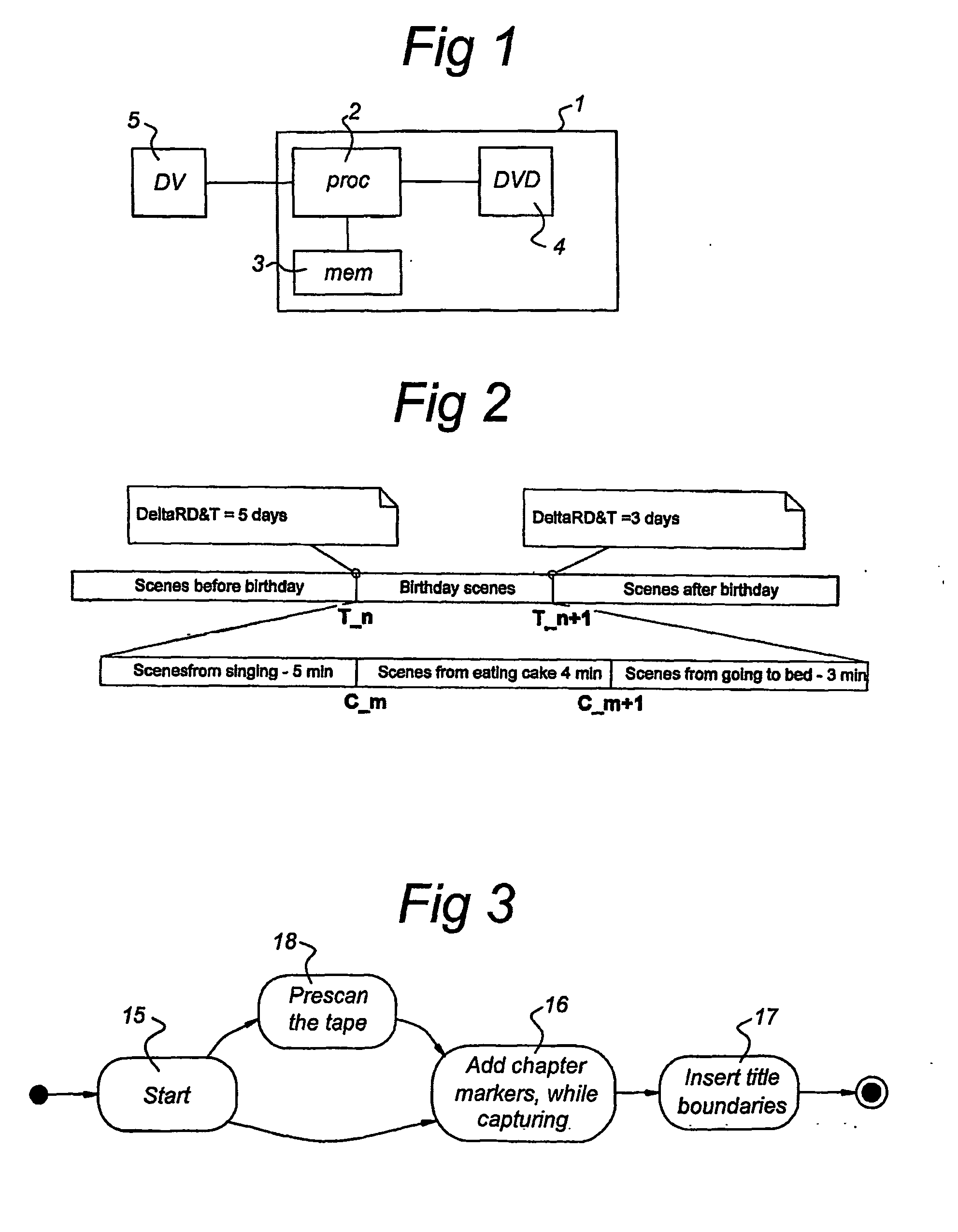
[0028] In FIG. 1, a schematic diagram is shown of a set-up of a recording system 1, e.g. a DVD recorder, comprising processing electronics 2, local memory 3 connected to the processing electronics 2, and a first recording medium 4, in this case a DVD disc. The processing electronics 2 and local memory 3 cooperate to provide the functionality of the recording system 1. The recording system 1 may be connected to a (video) data source 5, e.g. a DV camera, to record video footage from the DV camera from a second recording medium (e.g. a DV tape) to the first recording medium 4. This process is called capturing. When capturing the footage a title is created. A title is a playable entity that has an entry in a table of content (TOC) associated with the first recording medium 4. The user can access the TOC and select a title to play. The TOC may consist of key-frames, small icon pictures representing the title.

[0029] For one capturing session, one title is created. The title may be as lon...


PUM

PropertyMeasurementUnit
recording start timeaaaaaaaaaa
recording timeaaaaaaaaaa
recording time discontinuityaaaaaaaaaa

Abstract

Method and recording system for obtaining a data recording on a first medium, such as a DVD, from a data stream originating from a second medium, such as a DV tape. The data stream comprises a number of data segments each having a different recording start time. In the present invention, which may be used ‘on the fly’ and in combination with a pre scan, a recording segment of the data recording on the first medium is generated based on a determination of a duration of a present recording segment. A new recording segment is generated when a recording time discontinuity exceeds a threshold value, the recording time discontinuity being a difference between a recording end time of a first data segment and a recording start time of a next data segment.

Description

TECHNICAL FIELD [0001] The present invention relates to a method for obtaining a data recording, such as a (digital) video recording, on a first medium, such as a DVD, from a data stream originating from a second medium, such as a digital video tape, the data stream comprising a plurality of data segments or scenes each having a different recording start time. The method comprises generating a recording segment of the data recording on the first medium based on a determination of a duration of a present recording segment. [0002] In a further aspect, the present invention relates to a recording system for obtaining a data recording on a first medium from a data stream originating from a second medium, the data stream comprising a plurality of data segments each having a different recording start time, the recording system comprising input means for receiving the data stream from the second medium, output means for storing the data recording on the first medium, and processing means c...

Claims


Application Information

Patent Timeline
Patent Type & Authority Applications(United States)
IPC IPC(8): G11B3/64G11B20/10G11B27/031
CPCG11B20/10G11B2220/91G11B2220/2562G11B27/031
Inventor SCHIPPER, ALPHONSUS TARCISIUSSTANKOVIC, ZORANCZARKOWSKI, MICHAL
Owner KONINKLIJKE PHILIPS ELECTRONICS NV
Learn More