Method and system for controlling a network for power beam transmission

a power beam transmission and network control technology, applied in data switching networks, frequency-division multiplexes, instruments, etc., can solve the problems of limited flight altitude of low intensity of sunlight, and limited time and distance that can be achieved by aircraft operating on combustion engines. , to achieve the effect of increasing the range of travel of a mobile user node, increasing reliability and availability, and reducing the unit size of individual beam sources in the network

Active Publication Date: 2007-11-29
THE BOEING CO
View PDF99 Cites 33 Cited by
  • Summary
  • Abstract
  • Description
  • Claims
  • Application Information

AI Technical Summary

Benefits of technology

[0016]An advantage of the present invention is that mobile user nodes may rely on multiple beam sources for power, rather than limiting their dependence to a single beam source.
[0017]Another advantage of the present invention is that range of travel of a mobile user node is increased beyond the range of a single beam source by enabling handoffs between multiple source nodes.
[0018]A further advantage of the present invention is increased reliability and availability by having multiple sources of power.
[0019]Yet another advantage of the present invention is that the unit size of individual beam sources in the network can be decreased, which decreases overall cost per unit of power, and decreases the logistical burden.
[0020]Still another advantage of the present invention is increased range and reliability by the inclusion of relays in the architecture to provide pathways around airborne obstacles.
[0021]Another advantage of the present invention is the generality of the architecture and its interoperability, e.g., a source node may support multiple types of user nodes that it was not specifically designed to support, and a user node may use power from a variety of source nodes.

Problems solved by technology

Aircraft combustion engines that burn hydrocarbon fuels are limited in their flight altitude because at high altitudes, there is insufficient oxygen to sustain combustion.
Aircraft that operate on combustion engines are also limited in the total time and distance that can be achieved between landings, due to the weight and quantity of fuel that they must transport.
Some high-altitude airplanes have been powered by solar power, but sunlight has low intensity under the best circumstances and is unavailable at night.
However, limitations have been encountered with the operation of HELIOS and other solar-powered aircraft.
However, power beaming from a single beam power source to a single user node such as a small aircraft, has limited usefulness.
A single source may be configured with power beam characteristics that are incompatible with a particular aircraft—e.g., the power beam may be too powerful or too weak.
Since there is not a uniform standard for power beaming, interoperability becomes difficult, reducing the value of each type of aircraft and each type of source node.
Current ground-based power beam source nodes encounter additional obstacles to power transmission.
Atmospheric obstacles such as clouds or turbulence interfere with the power transmissions by scattering light.
Since some user nodes receive the power via arrays of photovoltaic cells that are limited in area, much of the transmitted power becomes unfocused due to such spreading and is lost.
Maintaining airborne surveillance is another challenge that cannot be effectively achieved using combustion propulsion, as political and military factors reduce airborne intelligence, surveillance and reconnaissance (ISR) below 100 thousand feet.
Providing for the needs and capabilities of multiple user nodes, source nodes, and relays to create a distributed power beaming system is a complex undertaking.
Such a system is unable to function properly without interoperability and the ability to represent various attributes and interactions between the nodes of the power-beaming network.

Method used


Image

  • Method and system for controlling a network for power beam transmission
  • Method and system for controlling a network for power beam transmission
  • Method and system for controlling a network for power beam transmission

Examples


Embodiment Construction

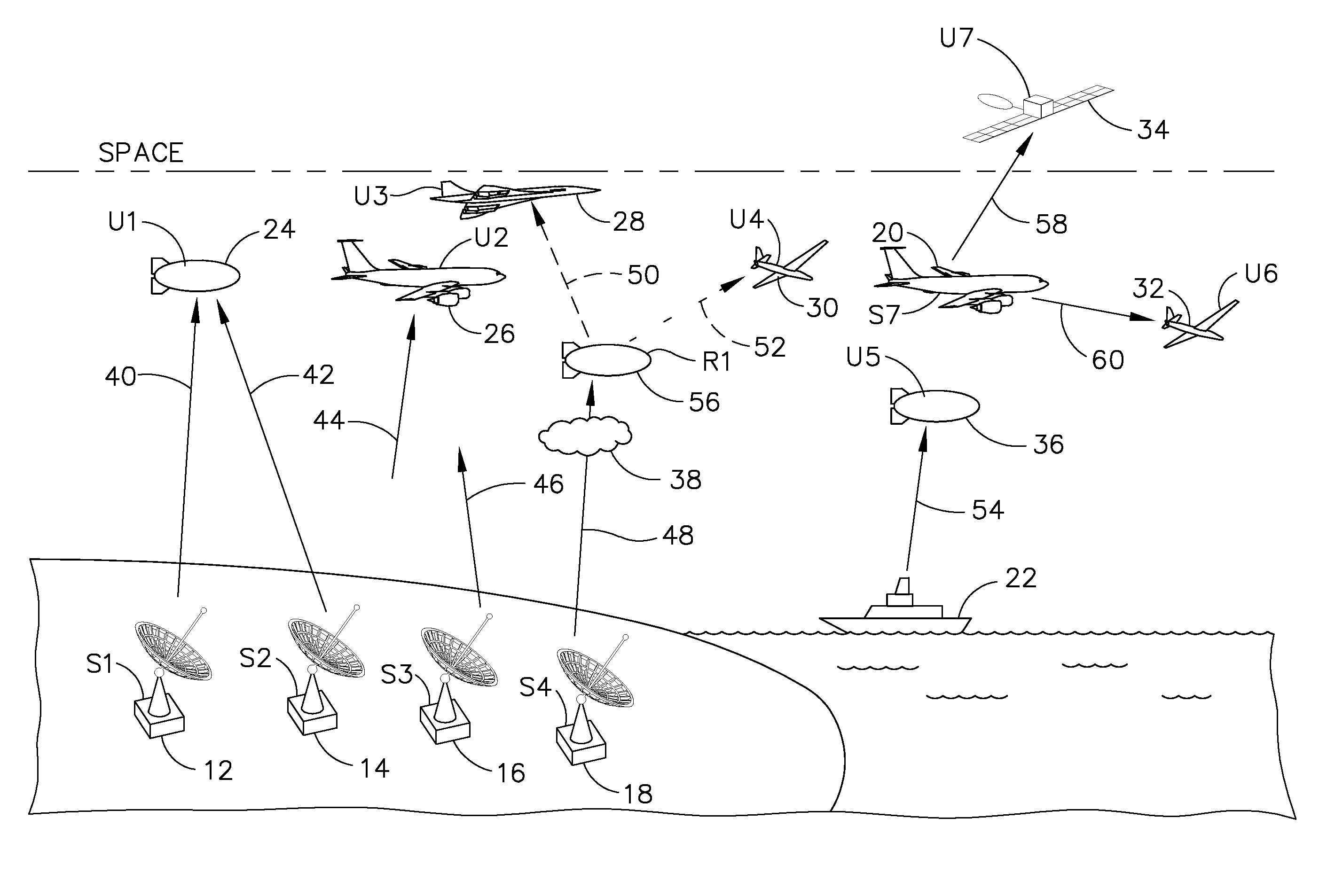
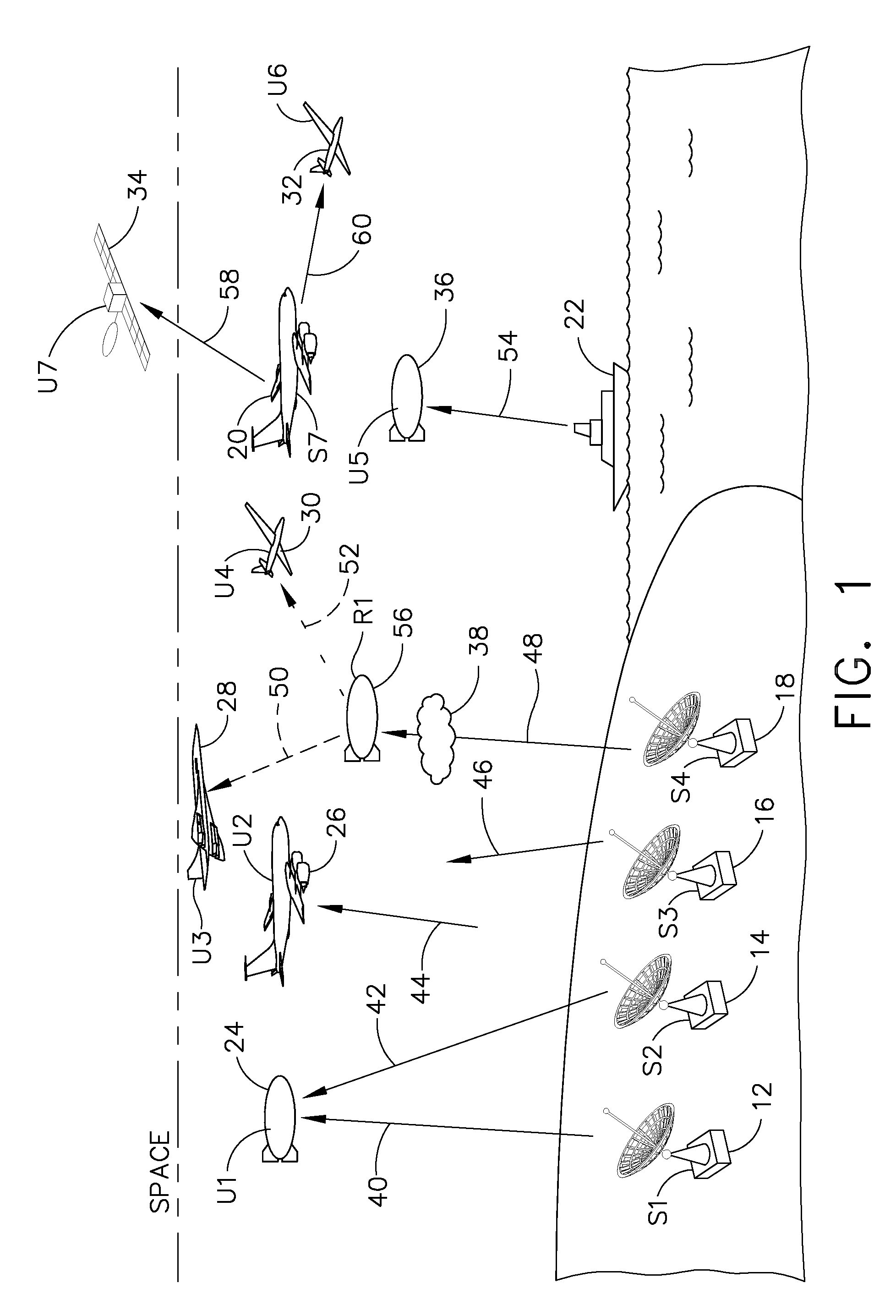
[0028]Referring to FIG. 1, an exemplary system of the present invention has a plurality of source nodes 12, 14, 16, 18, 20&22. Source nodes 12-22 include fixed nodes 12, 14, 16&18 and mobile nodes 20&22, and combinations thereof. The system also has beam-powered user nodes 24, 26, 28, 30, 32, 34&36 and communication systems (not shown) for each beam-powered user node 24-34 to request power from a plurality of source nodes 12-22. The user node 24-34 specifies a set of preferably predetermined parameters, including, e.g., an acceptable time interval, and acceptable parameters relative to the power beam, e.g., the wavelength of a power beam that the user node may receive, the pulse rate of the power beam, a duty cycle, engagement geometry, size of beam, etc. The system also includes one or more relays 56 for directing power beams around airborne obstructions 38.

[0029]Each source node 12-22 is configured to specify its power delivery capability, e.g., the wavelength of its power beam, t...


PUM


Abstract

A method of providing power beams via a network of source nodes. Source nodes are configured to receive requests for power beam service from airborne user nodes such as aircraft equipped with photovoltaic receivers. User nodes are configured to communicate a set of parameters, such as location, mobility, field of regard, one or more beam wavelengths compatible with the receiver, the beam wavelength further described with a maximum sustained power, duty cycle and pulse repetition rate. Source nodes publish parameters to a network control system. Source nodes publish their location, velocity vector, orientation, available beam capacity, and a schedule of user nodes currently receiving service from the node. Source nodes selectively receive requests from user nodes, and respond to the requests to satisfy the user node parameters. Relays may be used to avoid obstructions, and deconflicting sensors and obstruction sensors may be used detect unauthorized or unusable beam paths.

Description

FIELD OF THE INVENTION[0001]The present invention is directed to a method and system for controlling a network for power beam transmission, and more particularly to a system architecture for controlling beam power between multiple source nodes and user nodes.BACKGROUND OF THE INVENTION[0002]Aircraft combustion engines that burn hydrocarbon fuels are limited in their flight altitude because at high altitudes, there is insufficient oxygen to sustain combustion. Aircraft that operate on combustion engines are also limited in the total time and distance that can be achieved between landings, due to the weight and quantity of fuel that they must transport. Aircraft that do not rely on combustion engines can achieve higher flight altitude, as well as longer flight times, than aircraft that rely on combustion engines. Some high-altitude airplanes have been powered by solar power, but sunlight has low intensity under the best circumstances and is unavailable at night. For example, the HELIO...

Claims


Application Information

Patent Timeline
Patent Type & Authority Applications(United States)
IPC IPC(8): H04J1/16
CPCH02J17/00H02J50/30H02J50/50H02J50/60H02J50/80H02J50/20B64G1/428B64G1/44
Inventor TILLOTSON, BRIAN J.
Owner THE BOEING CO
Why Eureka
Try Eureka