Vent structure forcing a Z-pattern air flow

a vent structure and air flow technology, applied in ventilation systems, lighting and heating apparatuses, heating types, etc., can solve the problems of inability to generally achieve vent structures, inrush of such air, and large destruction, and achieve the effect of simple vent structure and inexpensive manufacturing

Active Publication Date: 2007-11-29
BRANDGUARD VENTS
View PDF18 Cites 28 Cited by
  • Summary
  • Abstract
  • Description
  • Claims
  • Application Information

AI Technical Summary

Benefits of technology

[0016]Another objective is to make a relatively simp

Problems solved by technology

However, during external brush fire conditions, the prior art vent structures are not generally capable of preventing fire brands from entering building spaces through prior art vent structures because heated air from such fires is known to move with great speed and force against building structures and pressure differentials between building interiors and highly heate

Method used


Image

  • Vent structure forcing a Z-pattern air flow
  • Vent structure forcing a Z-pattern air flow
  • Vent structure forcing a Z-pattern air flow

Examples


Embodiment Construction

[0027]The above described drawing figures illustrate the described apparatus and its method of use in at least one of its preferred, best mode embodiment, which is further defined in detail in the following description. Those having ordinary skill in the art may be able to make alterations and modifications what is described herein without departing from its spirit and scope. Therefore, it must be understood that what is illustrated is set forth only for the purposes of example and that it should not be taken as a limitation in the scope of the present apparatus and method of use.

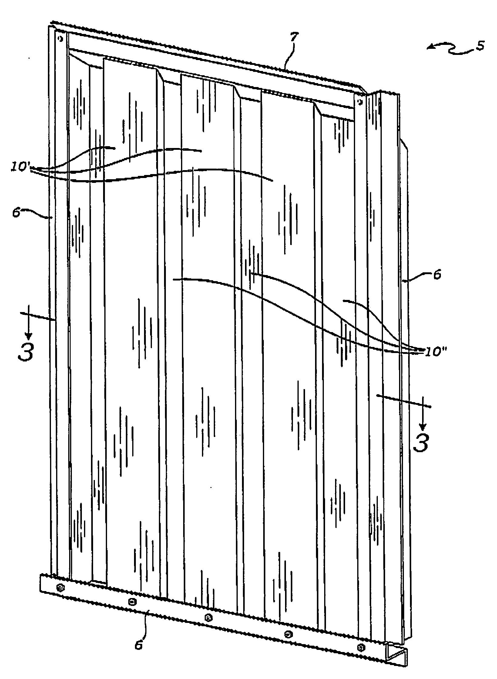
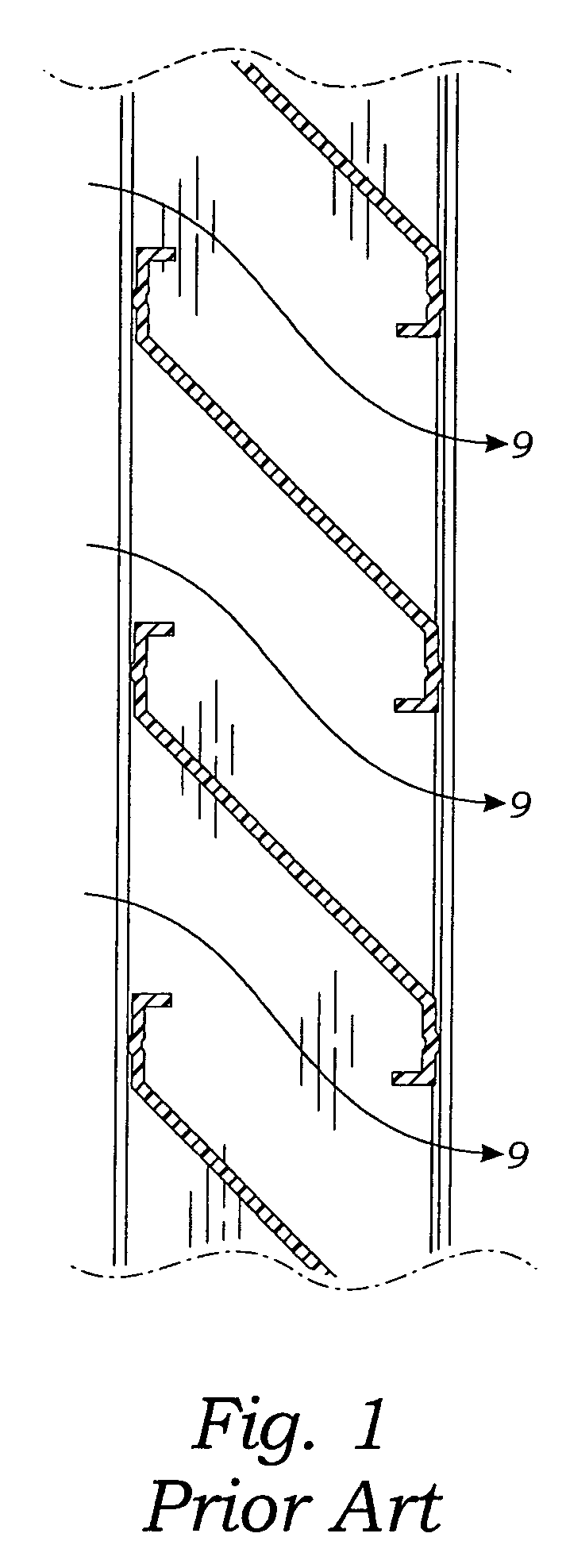
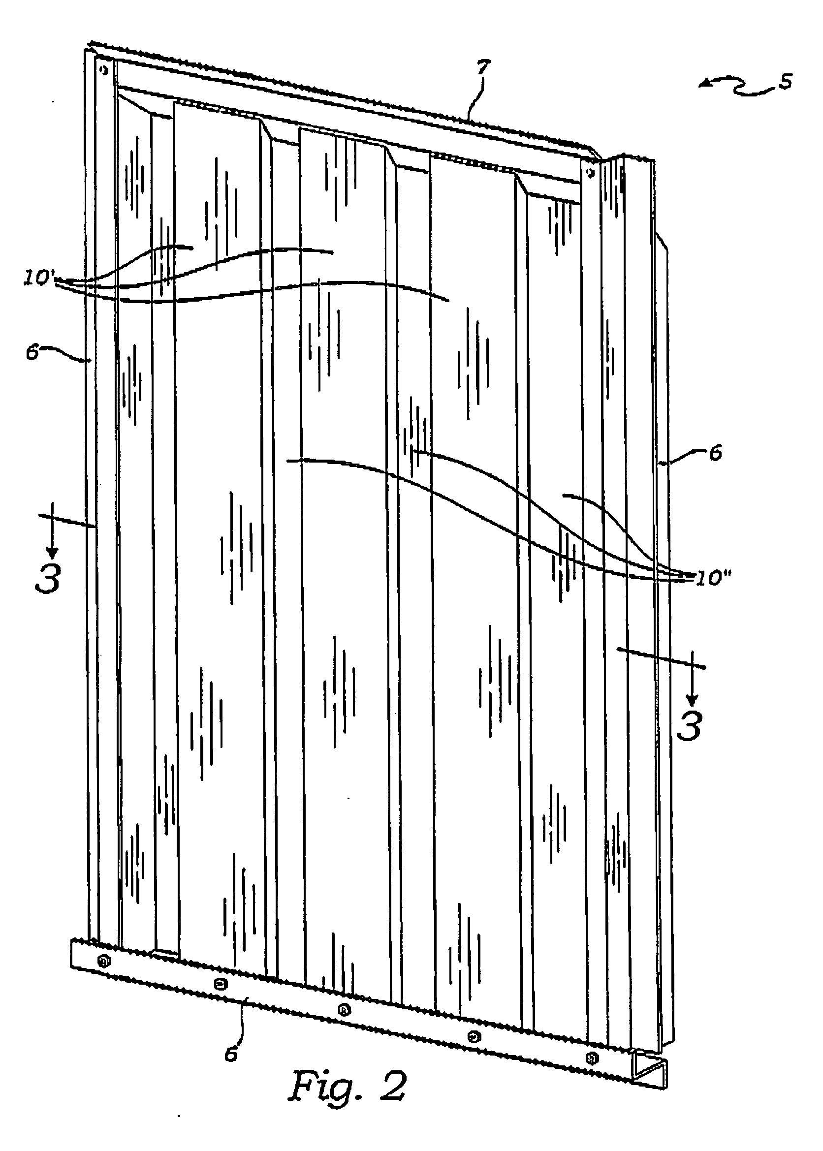
[0028]As can be seen in FIG. 1, the prior art teaches that it is beneficial to direct air flow through a static vent with some lateral movement, i.e., it is not possible to see through the vent directly. Described now in detail is a vent apparatus assembled in a box frame 5 as shown in FIG. 2. The box frame 5 is preferably made of aluminum sheet metal formed L-pieces or U-channels. Alternatively, these elem...


PUM


Abstract

A vent is mounted in a building wall so as to enable air exchange between the interior of the building and the outside environment. A first set of plural, spaced apart, air guide members and a second set of plural, spaced apart, air guide members are formed using elongate units each having a base element contiguous with opposing leg elements. The base elements of the first set of guide members are arranged in a first vertical plane, while the base elements of the second set of guide members are arranged in a second vertical plane, wherein the planes are in parallel horizontal mutual displacement. The leg elements of the two sets of air guide members are positioned and interlaced to force air flow moving through the apparatus is make a first right angle turn followed by a “Z” shaped turn and then a second right angle turn.

Description

CROSS-REFERENCE TO RELATED APPLICATIONS[0001]Not applicable.STATEMENT REGARDING FEDERALLY SPONSORED RESEARCH OR DEVELOPMENT[0002]Not applicable.THE NAMES OF THE PARTIES TO A JOINT RESEARCH AGREEMENT[0003]Not applicable.INCORPORATION-BY-REFERENCE OF MATERIAL SUBMITTTED ON A COMPACT DISC[0004]Not applicable.REFERENCE TO A “MICROFICHE APPENDIX”[0005]Not applicable.BACKGROUND OF THE INVENTION[0006]1. Field of the Present Disclosure[0007]This disclosure relates generally to vent and grill structures and more particularly to a vent with parallel vertically arranged elements formed so as to force air to flow in a “Z” pattern.[0008]2. Description of Related Art Including Information Disclosed Under 37 CFR 1.97 and 1.98[0009]Myint, U.S. 2003 / 00500006, discloses an air vent to safeguard the security of the public potable water system, especially in such enclosed structures as reservoirs and clear wells and other vital air vented installations against sabotages, vandalism and accidental contam...

Claims


Application Information

Patent Timeline
IPC IPC(8): F24F7/02
CPCF24F2007/003F24F13/082F24F2007/0025H05K5/0214
Inventor BERKOMPAS, BRENT
Owner BRANDGUARD VENTS
Why Eureka
Try Eureka