
Injection Device for Administering a Vaccine

Inactive Publication Date: 2007-11-29
CHILDRENS HOSPITAL MEDICAL CENT CINCINNATI
View PDF99 Cites 36 Cited by
  • Summary
  • Abstract
  • Description
  • Claims
  • Application Information

AI Technical Summary

Benefits of technology

[0012] The present invention relates to improvements in an injection device configured for self-administering painlessly an injectable liquid composition, such as a vaccine or medicament. The device can be used in a method for providing a substantially painless injection of the injectable liquid composition to a patient that does not require the use of an anesthetic, that does not require the medical personnel to spend a substantial amount of time performing the injection procedure, that is relatively simple and inexpensive to prepare and operate, and that provides a relatively high degree of safety for both the medical personnel and for the patient. The device can be manually powered, or can have self-contained power for at least inserting the injection needle into the patient.

Problems solved by technology

Receiving an injection by such a conventional device can be a very traumatic experience, particularly for a child.
The child's fears, and that of the child's parent, can become a significant medical problem if it leads to the child not receiving a required vaccination.
These fears are predominately caused by pain that is associated with injections given by conventional injection devices and methods.
We have found that the pain associated with an injection is related to the size of the needle and the flow rate at which the medication is injected.
It has been found that the amount of pain or discomfort experienced by a patient increases as the outside diameter of the needle increases.
It is believed that high flow rates of medication injection (e.g., about 0.5-2 ml per second) into the patient can tear internal tissue and cause pain.
The tearing of tissue is caused by the build-up of excessive pressure within the tissue when the surrounding tissue is unable to quickly absorb the injected medication.
While the injection of a medication at a relatively slow flow rate is more comfortable for the patient, the increased amount of time the syringe remains in the hand of the medical personnel can make the technique tiring for such personnel as well as the patient.
In addition, small vibrations or disturbances of the needle caused by movement of the medical personnel or the patient can result in pain to the patient.
It is extremely difficult, if not impossible, to deliver a steady, very slow flow of medication from a hand-operated syringe (the human thumb depressing the syringe plunger) over an extended amount of time.
It has also been found that the sight of the hypodermic needle by itself is often enough to cause many patients to become anxious and tense.
This reaction in turn may cause the patient's muscles to become tight and hard, making needle penetration even more difficult and painful.
One such method includes the application of a topical anesthetic to the injection site on the patient's skin prior to the injection, which itself can be painful.
While this method has reduced some of the discomfort associated with injections, the topical anesthetic does not substantially penetrate the skin into the deeper skin and muscle tissue, and can take significant time (up to 45 minutes) to show effects.
Unfortunately, injecting an anesthetic into a patient is not always desirable and the technique is relatively expensive and impractical for many routine injection procedures.
Despite the taking of special precautions, there still remains the possibility of an accidental needle contact and attendant injury.

Method used


Image

  • Injection Device for Administering a Vaccine
  • Injection Device for Administering a Vaccine
  • Injection Device for Administering a Vaccine

Examples


first embodiment

[0093] the invention is shown in FIGS. 1-3, 3A, and 4-28. The device includes a housing, shown in FIGS. 1-3, 3A, and 4-9, and a cylindrical syringe cartridge shown in FIGS. 10-19. The use and operation of the device for manually self-administering a painless injection is illustrated in FIGS. 20-28. A device having a housing for retaining a plurality of cylindrical syringe cartridges is shown in FIGS. 29-31. FIGS. 32-25 show a separable base and means for attaching the device to a patient's skin.

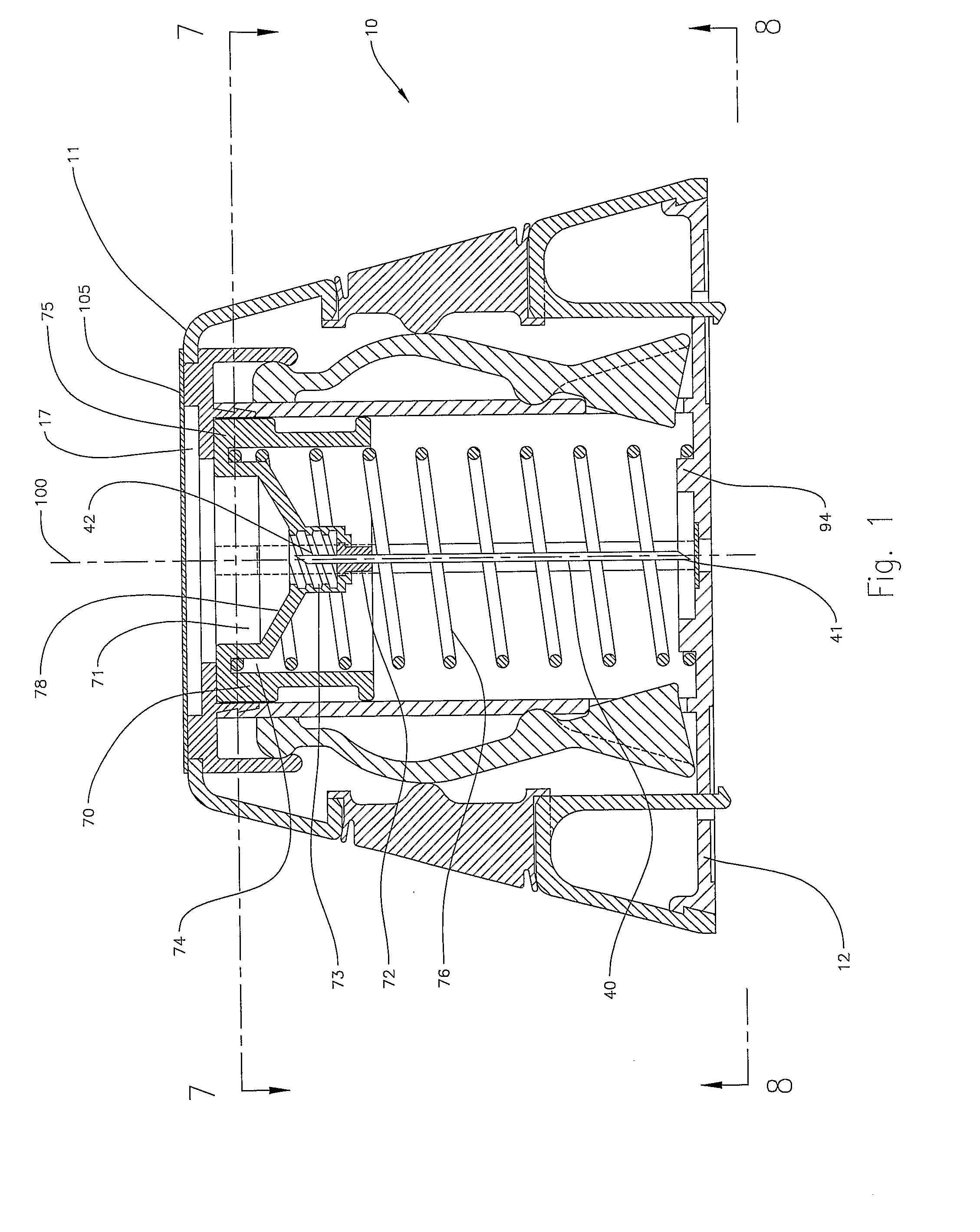
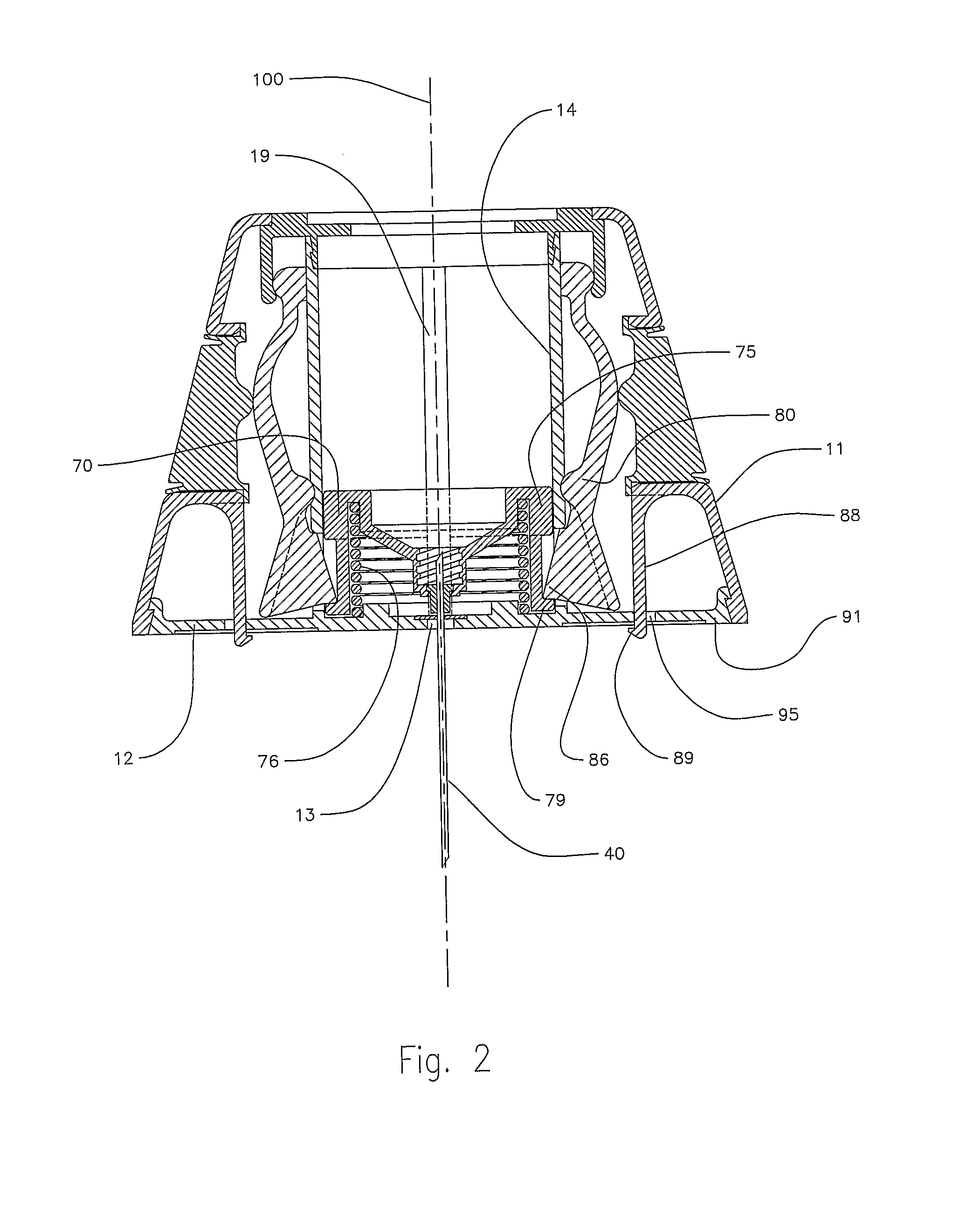
[0094]FIGS. 1-8 show an assembled housing 10 in various views and aspects. FIG. 1 shows the housing 10 having an outer body 11, a needle carriage 70, a means for retaining a reservoir for an injectable liquid composition, and a base 12 for placement of the device against the skin of a patient. The carriage 70 is configured for movement along an axial centerline 100 in a direction perpendicular to the base 12. The cylindrical carriage has a cylindrical recess 71 having a tapered bottom 78, tha...

second embodiment

[0128] In the present invention, the device employing a separable base 92 can comprise a device that comprises an on-board power means, as described above, for inserting the injection needle, and optionally, injecting the medication and retracting the needle. As shown in FIG. 19, and referring to FIG. 11, the syringe cavity can comprise a self-contained power source in the form of the compressed pressurizing spring 33. In the illustrated embodiment, the compressed spring is exerting its force upon the vaccine contained in the cavity 66, placing it under pressure. Optionally, in this alternative embodiment, the cylindrical body 31 can be configured with a retainer pin that withholds the pressurizing spring 33 (and therefore pressure upon the vaccine) from contact with the plunger 24, or withholds the plunger 24 itself, until released by a releasing means, such as an annular retaining ring having a tab extending through the cylinder wall 31.

third embodiment

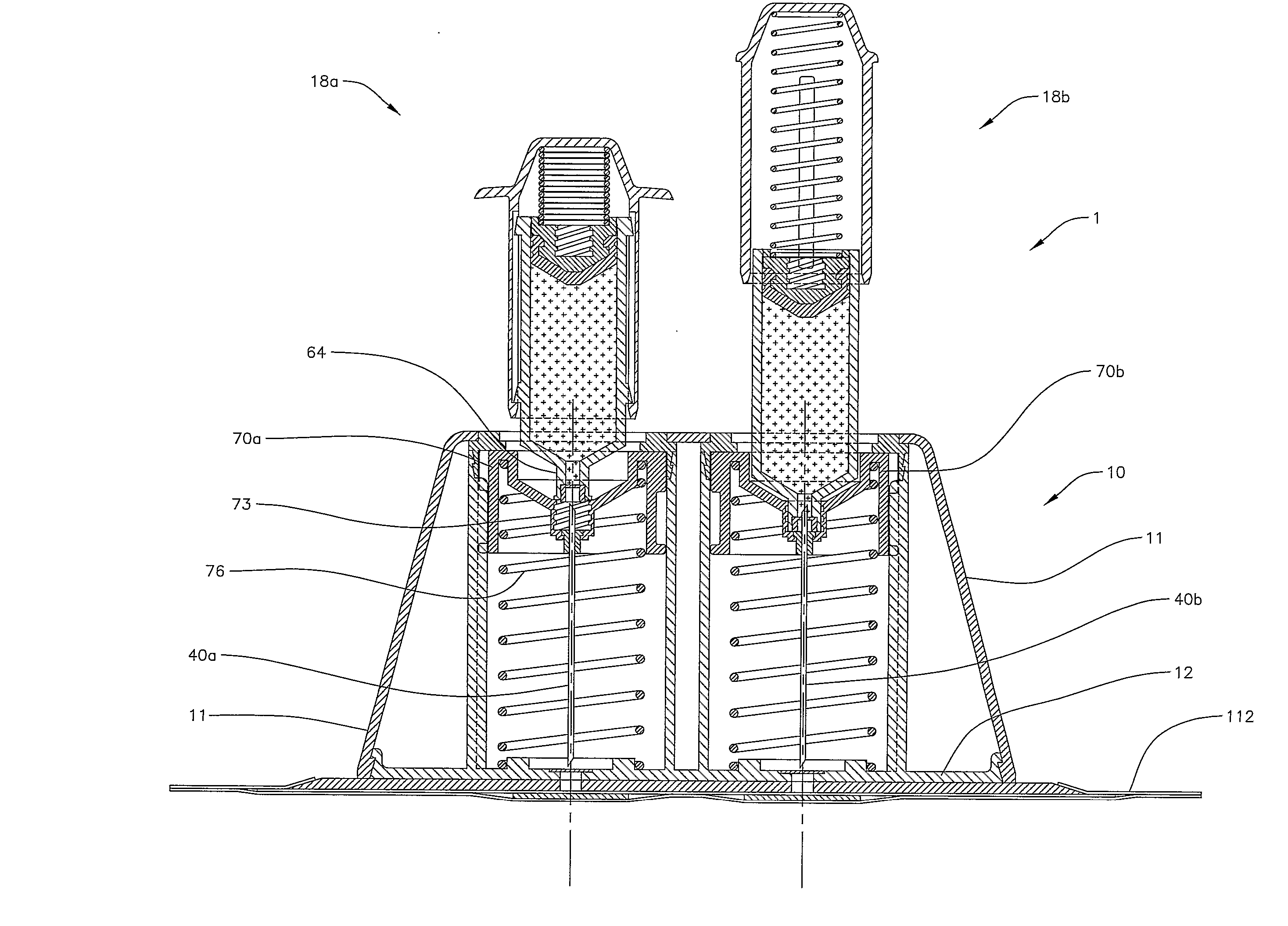
[0129] In the present invention, a device can have a plurality of injection needles and reservoirs disposed within the housing. The device can provide for injecting at least two injectable liquid compositions to a patient. FIGS. 29 and 30 show a top plan view and an elevation view of a device 1 for injecting at least two liquid compositions from separate reservoirs contained in the housing. As shown in FIG. 31, the device 1 can comprise a housing 10 and base 12 for two needle carriages 70a and 70b and two injection needles 40a and 40b, which can be configured to be separately and independently manipulated for insertion, injection and retraction, as described herein above.

[0130] Alternatively, the two needle carriages and needles can be configured for simultaneous insertion, injection, and retraction using shared elements, including a shared, dual-recess needle carriage, and a dual unitary pressurizing assembly.

[0131] If only one injectable liquid composition will be administered, t...


PUM


Abstract

An injection device that self-administers a painless vaccine injections. The injection device (10) can be secured to the patient's skin via a separable base portion (12) of the housing of the device, which can be separated from the device when removing the housing and syringe assemblies for disposal. The injection device can provide a method for substantial amount of time performing the injection procedure, that is relatively simple and inexpensive to perform and operate, and that provides a relatively high degree of safety for both the medical personnel and for the patient. The injection device is configured for easy handling, and is manually-powered by the use of the hand or fingers of the medical technician. The device can also comprise a plurality of vaccine syringes at the same time with a single device.

Description

BACKGROUND [0001] The present invention relates to the injection of vaccines and other medication and, more particularly, to an improved injection device that can be used in a method for administering vaccine injections painlessly for a patient. [0002] Conventional medical injection devices for injecting medication into the muscle or tissue of a patient typically comprise some form of a manual hypodermic syringe. Generally speaking, a hypodermic syringe consists of a cylindrical barrel having a chamber that provides a reservoir for a liquid medication, a distal end adapted to be connected to a hollow hypodermic needle and for placing one end of the needle into flow communication with the medication contained within the chamber, and a proximal end adapted for receiving a stopper and plunger assembly. The stopper and plunger assembly includes a stopper effective for moving along the barrel chamber and an elongated plunger effective for causing movement of the stopper. The needle of th...

Claims


Application Information

Patent Timeline
IPC IPC(8): A61M5/30A61B17/32A61M5/19A61M5/20A61M5/24A61M5/31A61M5/32A61M5/34A61M5/42A61M5/48A61M5/50
CPCA61M5/19A61M2205/583A61M5/24A61M5/2429A61M5/2466A61M5/3129A61M5/3257A61M5/347A61M5/427A61M5/484A61M5/50A61M2005/3106A61M2005/3114A61M2005/3128A61M2005/3139A61M2005/325A61M5/2033
Inventor WALL, ERIC JAMESWARD, JARVISNESBITT, CHRISTOPHER J.NESBITT, DANIEL FREDERICK
Owner CHILDRENS HOSPITAL MEDICAL CENT CINCINNATI
Learn More