Fenestrated bone tap and method

a bone tap and fenestration technology, applied in bone drill guides, medical science, surgery, etc., can solve the problems of osteoporotic vertebrae that cannot be treated weakened or softened bone may be difficult to treat with conventional stabilization techniques, and spinal stabilization procedures may fail in osteoporotic vertebrae, etc., to prevent the backflow of fluid and augment the fixation of bone fasteners

Inactive Publication Date: 2007-11-29
ZIMMER BIOMET SPINE INC +1
View PDF31 Cites 39 Cited by
  • Summary
  • Abstract
  • Description
  • Claims
  • Application Information

AI Technical Summary

Benefits of technology

[0012] In some embodiments, a fenestrated bone tap may be used to introduce bone cement into a portion of damaged or diseased bone to stabilize and / or strengthen the bone. The fenestrated bone tap may stabilize or strengthen a vertebra, a sacrum, a femur, a tibia, a radius, and / or a humerus. The fenestrated bone tap may be used to stabilize other types of bone. In some embodiments, a fenestrated bone tap may be used to introduce material into bone tissue in addition to or in lieu of bone cement. In some embodiments, a fenestrated bone tap may be used to introduce medicine (e.g., antibacterial agents), synthetic bone material, bone growth proteins and / or other substances into bone. In some embodiments, one or more bones adjacent to a target bone may be augmented before, during, or after augmentation of the target bone.

Problems solved by technology

Weakened or softened bone may be difficult to treat with conventional stabilization techniques.
For example, spinal stabilization procedures may fail in osteoporotic vertebrae.
Osteoporosis (i.e., a bone condition characterized by reduction in bone mass and increased susceptibility to fracture after minimal trauma) may cause loosening and / or pullout of bone fasteners, possibly leading to failure of the spinal stabilization system.
A fenestrated bone screw that has been cured in place may be difficult to remove should a subsequent procedure be necessary due to infection, further injury, and / or other causes.
Limitations of such methods of cement introduction may include retrograde flowback of bone cement along the needle and limited vertebral body fill.
Systemic complications from bone cement leakage may include fever, infection, pulmonary embolism, fat embolism, hypoxia, hypotension, myocardial infarction, and sudden death.
In addition to iliac crest autograft, the use of allograft bone and various graft extenders is also known; however, by themselves these materials can be unreliable for stimulating fusion without the addition of autograft.
As such, local bone from laminectomy sites can be used, but this is often limited in supply.

Method used


Image

  • Fenestrated bone tap and method
  • Fenestrated bone tap and method
  • Fenestrated bone tap and method

Examples


Embodiment Construction

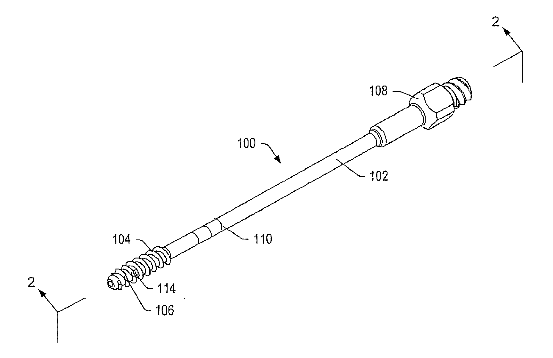
[0035] A bone tap may be used to form a threaded opening of a desired depth in a bone. In an embodiment, a bone tap may be used to prepare an opening in a bone for insertion of a bone fastener (e.g., a bone screw) to be used as part of a spinal stabilization system. In some embodiments, a bone tap may include a passage and fenestrations for introducing bone cement into bone proximate a distal portion of the tap. The bone cement may augment fixation of a bone fastener. Bone cement augmentation may increase axial pullout strength and transverse bending stiffness of a bone / fastener interface in a spinal stabilization system. In certain embodiments, a tap may be used to introduce bone cement into a portion of weakened, damaged or diseased bone (e.g., a vertebra) to stabilize and / or strengthen the bone.

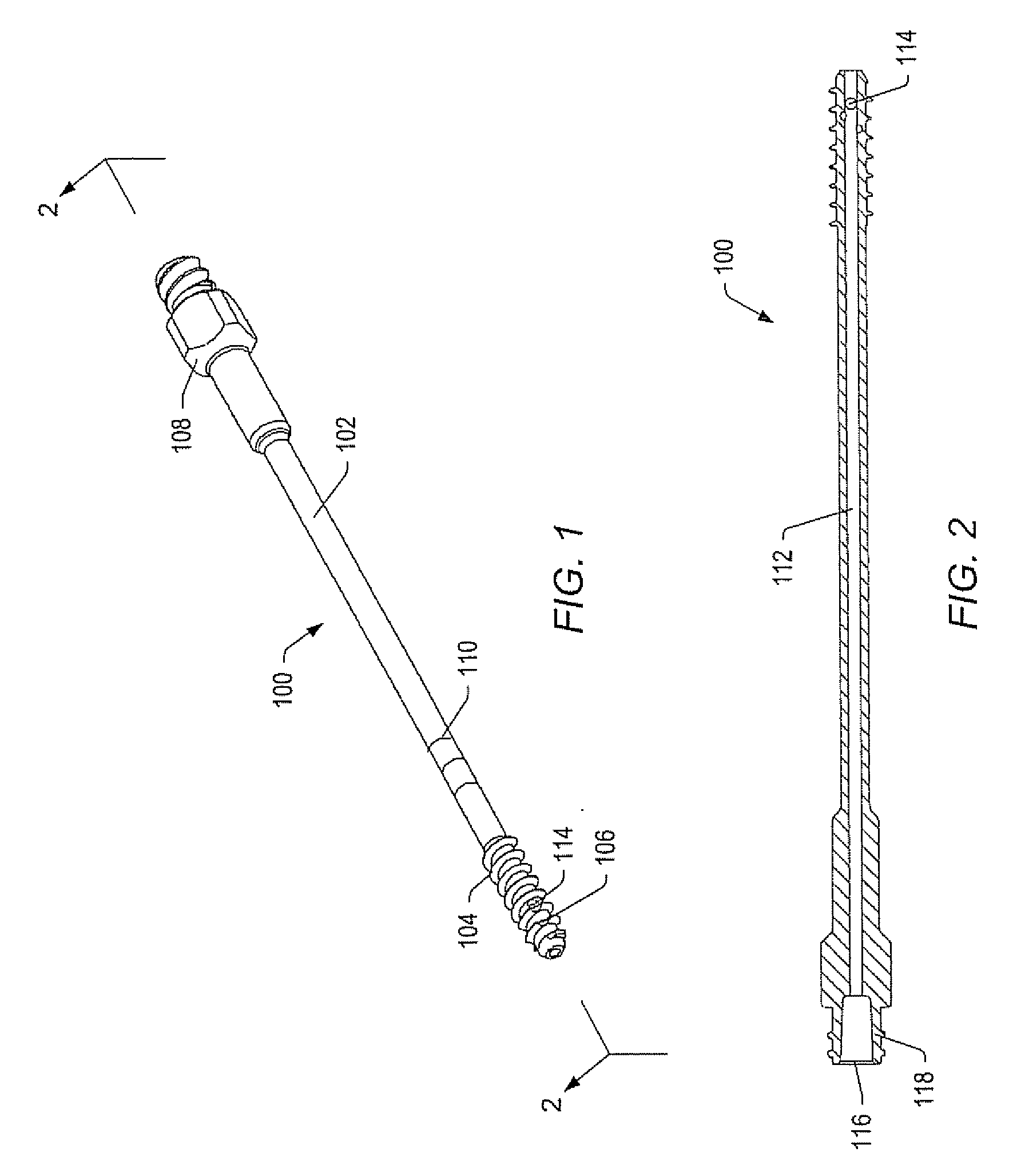
[0036]FIG. 1 depicts an embodiment of bone tap 100. Bone tap 100 may be made of materials, including, but not limited to, stainless steel, titanium, and / or plastic. Bone tap 100 may inclu...


PUM


Abstract

A bone tap may be used to deliver and / or aspirate fluid to and / or from a bone. The bone tap may include a passage. A distal portion of the bone tap may be threaded. In some embodiments, openings in a distal portion of the bone tap may communicate with the passage. The bone tap may be driven into bone, and material may enter or exit the bone through the openings and passage.

Description

CROSS-REFERENCE TO RELATED APPLICATION [0001] This application is a continuation-in-part application of U.S. Ser. No. 10 / 717,379, filed Nov. 19, 2003, entitled “Fenestrated Bone Tap and Method”. The full disclosure of this application is hereby incorporated by reference.BACKGROUND [0002] 1. Field of the Invention [0003] The present invention generally relates to apparatus and methods for treatment of human bone. Embodiments of the invention relate to spinal stabilization systems and methods that may be used to treat damaged or diseased bone. Embodiments of the invention relate to systems and methods used to augment fixation of bone fasteners. Embodiments of the invention relate to systems and methods used in vertebroplasty. Embodiments of the invention relate to systems and methods used in spinal arthrodesis. [0004] 2. Description of Related Art [0005] Bone may be treated for damage or degeneration arising from a variety of causes, such as trauma, disease, and / or aging. For example,...

Claims


Application Information

Patent Timeline
Patent Type & Authority Applications(United States)
IPC IPC(8): A61B17/58A61B17/02A61B17/16A61B17/17A61B17/88A61B19/00
CPCA61B17/1655A61B17/1671A61B17/1757A61B2019/462A61B17/8891A61B2017/0256A61B2019/306A61B17/8875A61B2090/036A61B2090/062
Inventor FRANKEL, BRUCE M.KOYSH, SCOTT D.HUNTER, NATALIE S.
Owner ZIMMER BIOMET SPINE INC
Why Eureka
Try Eureka