Air conditioning system

a technology of air conditioning system and compressor, which is applied in the direction of refrigeration components, transportation and packaging, light and heating equipment, etc., can solve the problems of excessive control value of heat load exerted on the evaporator at the start of operation, and achieve the effect of reducing the freezing of the evaporator and maximizing the capacity of the compressor

Active Publication Date: 2007-12-06
DENSO CORP
View PDF9 Cites 25 Cited by
  • Summary
  • Abstract
  • Description
  • Claims
  • Application Information

AI Technical Summary

Benefits of technology

[0016]In this case, when the control value setting condition for setting the driving output of the compressor is detected after the startup of the compressor, the control value is determined based on at least one of the pressure of refrigerant in the refrigerant cycle device and the outside air temperature. Therefore, the operation at an excessive control value with respect to the heat load exerted on the evaporator at the startup can be restricted. Thus, the freeze of the evaporator can be reduced, and the capability of the compressor can be efficiently provided without being excessively lowered.

Problems solved by technology

Therefore, the operation at an excessive control value with respect to the heat load exerted on the evaporator at the startup can be restricted.

Method used


Image

  • Air conditioning system
  • Air conditioning system
  • Air conditioning system

Examples


embodiments

First Embodiment

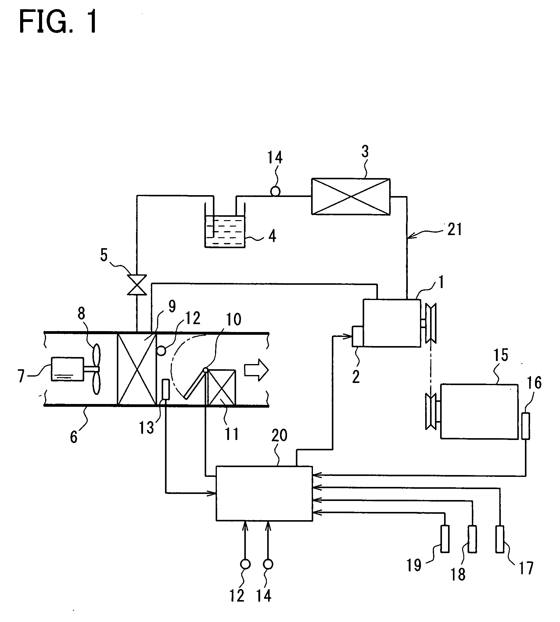
[0031]An air conditioning system for a vehicle according to a first embodiment of the present invention will be described with reference to FIGS. 1-7.

[0032]The air conditioning system has an air conditioner case 6 in which apparatuses for air-conditioning are housed, a refrigerant cycle device 21, and a control unit 20. Refrigerant for absorbing heat from blown air to cool blown air is circulated in the refrigerant cycle device 21 to flow through an evaporator 9 which is housed in the air conditioner case 6. The control unit 20 controls a driving output of a compressor 1 (which discharges refrigerant to the side of evaporator 9) by adjusting (changing) the control value of the compressor 1, to control the capability of the compressor 1.

[0033]The air conditioner case 6 can be used for a front-seat air conditioner unit and arranged in an instrument panel at the front portion of the vehicle to air-condition the front seat side of the passenger compartment. Moreover, the...

second embodiment

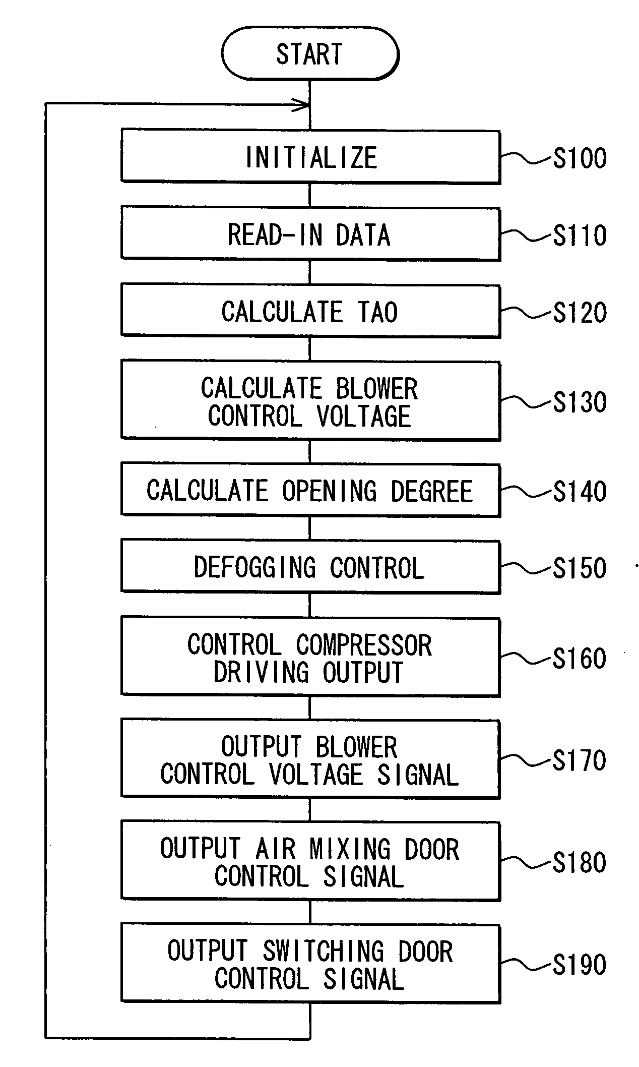
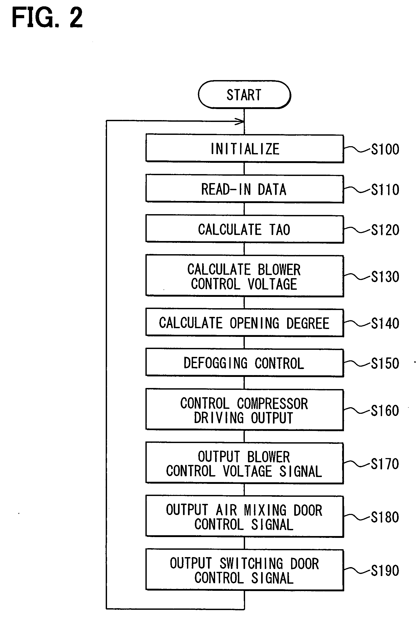
[0094]A second embodiment of the present invention will be described with reference to FIG. 7 which shows the subroutine of step S160 (that is, driving output step) in FIG. 2.

[0095]The control procedure of the driving output step of the compressor 1 according to the second embodiment is different from that of the first embodiment only at step S410 shown in FIG. 7. That is, the subroutine (shown in FIG. 3) of step S160 (in FIG. 2) is provided with step S410 shown in FIG. 7 instead of step S310.

[0096]In this case, at first, it is determined at step S300 whether or not the current driving of the compressor is the initial driving since the ignition switch becomes ON so that the control unit 20 is power-supplied. In the case where it is determined that the driving for this time is the initial driving, step S410 will be performed.

[0097]At step S410, the control value G2 for determining the driving output of the compressor 1 is calculated. In this case, the control value G2 is calculated b...

third embodiment

[0109]A third embodiment of the present invention will be described with reference to FIG. 8 which shows the subroutine of step S160 in FIG. 2.

[0110]In this case, steps S500, S550, S560 and S570 shown in FIG. 8 are respectively same with steps S300, S330, S340 and S350 in the subroutine shown in FIG. 3.

[0111]At first, when it is determined by the control unit 20 at step S500 that the driving of the compressor for this time is the initial driving since the ignition switch becomes ON so that the control unit 20 is power-supplied, step S510 will be performed.

[0112]At step S510, it is determined whether or not the outside-air temperature TAM detected by the outside air sensor 18 is lower than or equal to a predetermined temperature. In the case where it is determined at step S510 that the outside-air temperature (related to heat load of evaporator 9) is higher than the predetermined temperature, it is considered that the possibility for the evaporator 9 to freeze is low so that the abov...


PUM


Abstract

An air conditioning system for a vehicle has a refrigerant cycle device which has an evaporator and a compressor and in which refrigerant is discharged from the compressor to be evaporated in the evaporator so that air passing the evaporator is cooled to be blown into a passenger compartment of the vehicle. The control unit drives the compressor at a control value which is determined based on at least one of a pressure of the refrigerant in the refrigerant cycle device and an outside-air temperature outside the passenger compartment, when the control unit actuates the compressor.

Description

CROSS REFERENCE TO RELATED APPLICATION[0001]This application is based on a Japanese Patent Application No. 2006-157833 filed on Jun. 6, 2006 and a Japanese Patent Application No. 2007-131004 filed on May 16, 2007, the disclosures of which are incorporated herein by reference.FIELD OF THE INVENTION[0002]The present invention relates to an air conditioning system. The air conditioning system can be suitably used for a vehicle, for example.BACKGROUND OF THE INVENTION[0003]Generally, with reference to JP-5-85142A, an air conditioning system for a vehicle performs a PID control based on an actual value of an air temperature of a downstream side with respect to an evaporator at an outlet portion of the evaporator of a refrigerant cycle and a target value of the air temperature. In the air conditioning system, the capacity of the compressor is adjustable according to a calculated control value.[0004]However, as shown in FIG. 11, in the PID control of the air conditioning system disclosed i...

Claims


Application Information

Patent Timeline
Patent Type & Authority Applications(United States)
IPC IPC(8): B60H1/00F25B49/00
CPCB60H1/321F25B2700/21173B60H2001/3261B60H2001/3263B60H2001/3273B60H2001/3275F25B47/006F25B49/022F25B2500/19F25B2500/26F25B2600/0272F25B2700/2104F25B2700/2106F25B2700/2117B60H2001/3251
Inventor HONDA, KATSUHIKOWAKISAKA, TAKESHI
Owner DENSO CORP
Why Eureka
Try Eureka