

Rotary Valve Construction
- Summary
- Abstract
- Description
- Claims
- Application Information
AI Technical Summary
Benefits of technology
Problems solved by technology
Method used
Image

Examples
first embodiment
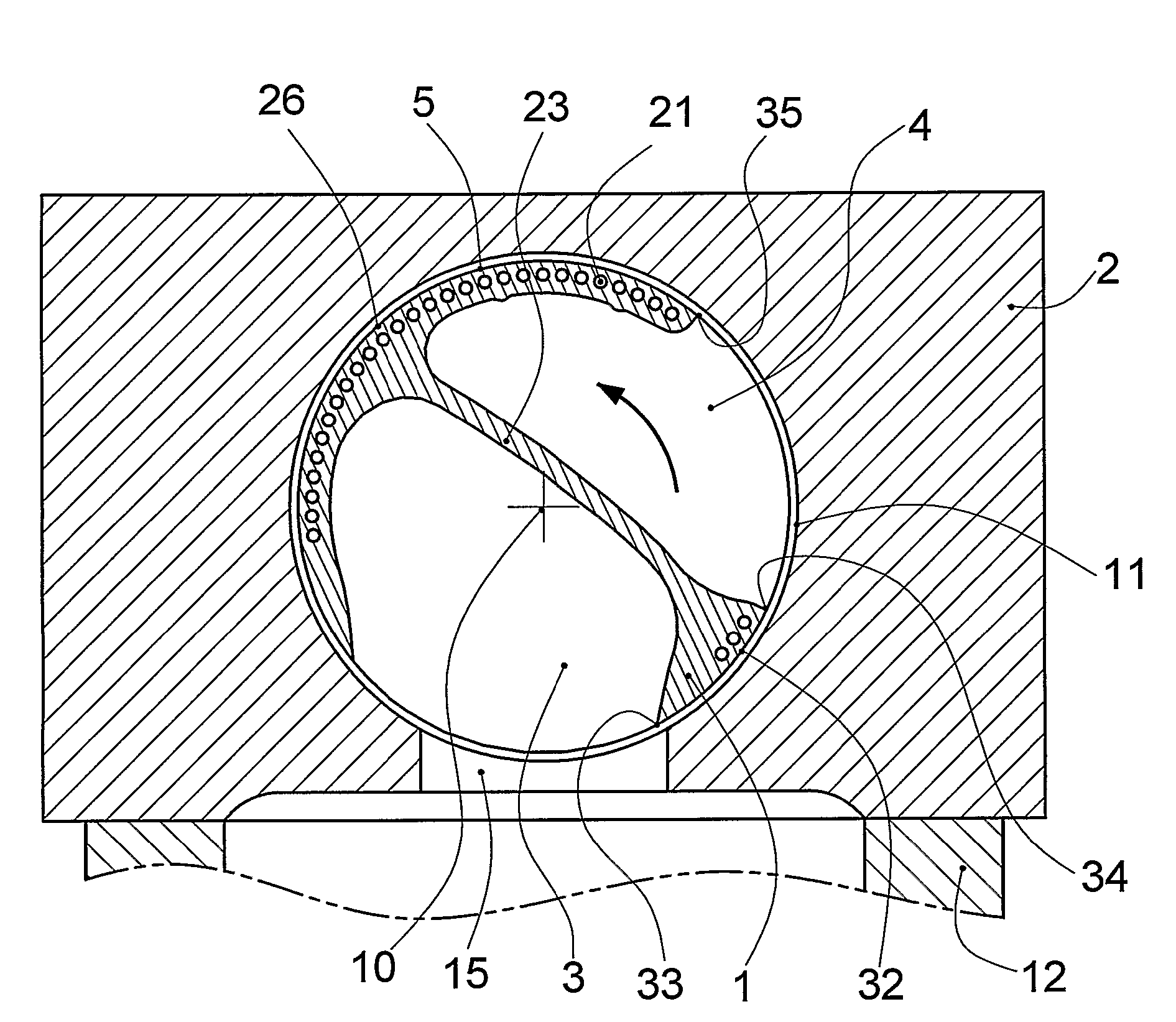
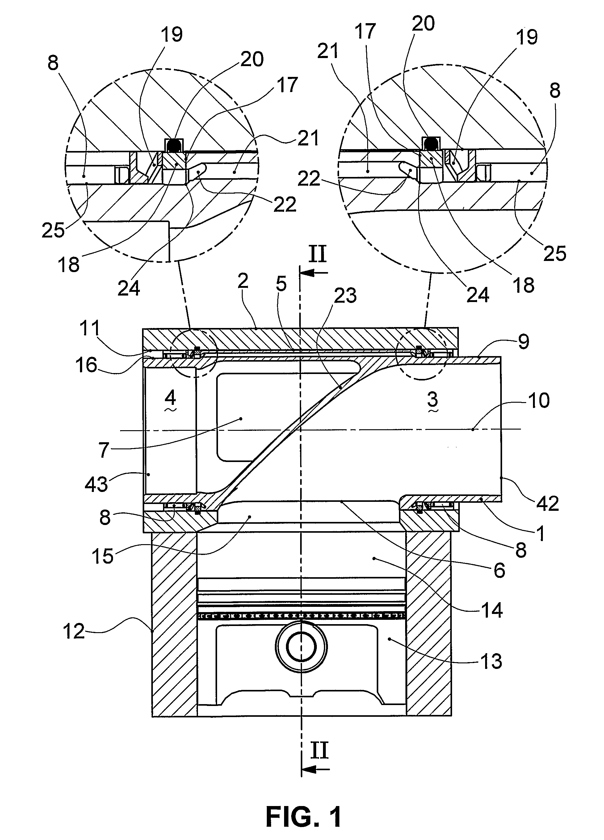
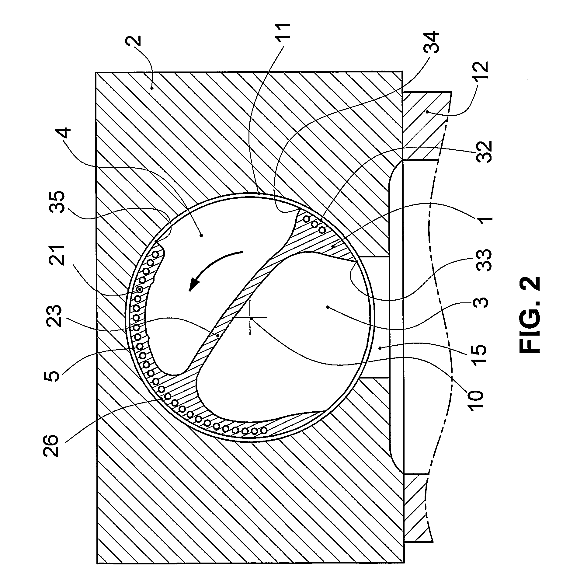
[0055]FIG. 1 depicts a rotary valve assembly according to the present invention comprising a valve 1 and a cylinder head 2. Valve 1 has an inlet port 3 and an exhaust port 4. Valve 1 has a centre portion 5 of constant diameter with an inlet portion 9 of reduced diameter on one side and exhaust portion 16 of reduced diameter on the other side. Inlet portion 9 extends between centre portion 5 and the inlet end 42 of valve 1. Exhaust portion 16 extends between centre portion 5 and the exhaust end 43 of valve 1. Inlet port 3 extends from inlet end 42 of valve 1 and terminates at inlet opening 6 in the periphery of centre portion 5. Exhaust port 4 extends from exhaust end 43 and terminates at exhaust opening 7 in the periphery of centre portion 5. Inlet port 3 and exhaust port 4 are separated by a common wall 23. Valve 1 is supported by bearings 8 to rotate about axis 10 in cylinder head 2. Bearings 8 support the periphery of inlet portion 9 and exhaust portion 16. Bearings 8 allow valve...
second embodiment
[0080] However, axial passages 21 are relatively expensive to machine due to their small diameter and long length. This issue is addressed by the present invention shown in FIG. 6 whereby valve 1 is manufactured from several pieces welded together. Axial passages 21 are formed in the outer diameter of valve inner body 28. In this case axial passages 21 are no longer necessarily round in cross-section or axially extending. Axial passages 21 may be replaced by passages that extend between the exhaust portion and the inlet portion but follow a diagonal, curvilinear or other path. Axial passages 21 are no longer confined by manufacturing considerations to the very low aspect ratios of those valves with machined holes. However, they should maintain a low aspect ratio to ensure structural efficiency.
[0081] Valve outer body 29 is shrunk over valve inner body 28 and welded to valve inner body 28. At a minimum, valve outer body 29 must be welded to valve inner body 28 adjacent to inlet openi...
PUM
 Abstract
Description
Claims
Application Information