

Wire electric discharge machine
- Summary
- Abstract
- Description
- Claims
- Application Information
AI Technical Summary
Benefits of technology
Problems solved by technology
Method used
Image

Examples
Embodiment Construction
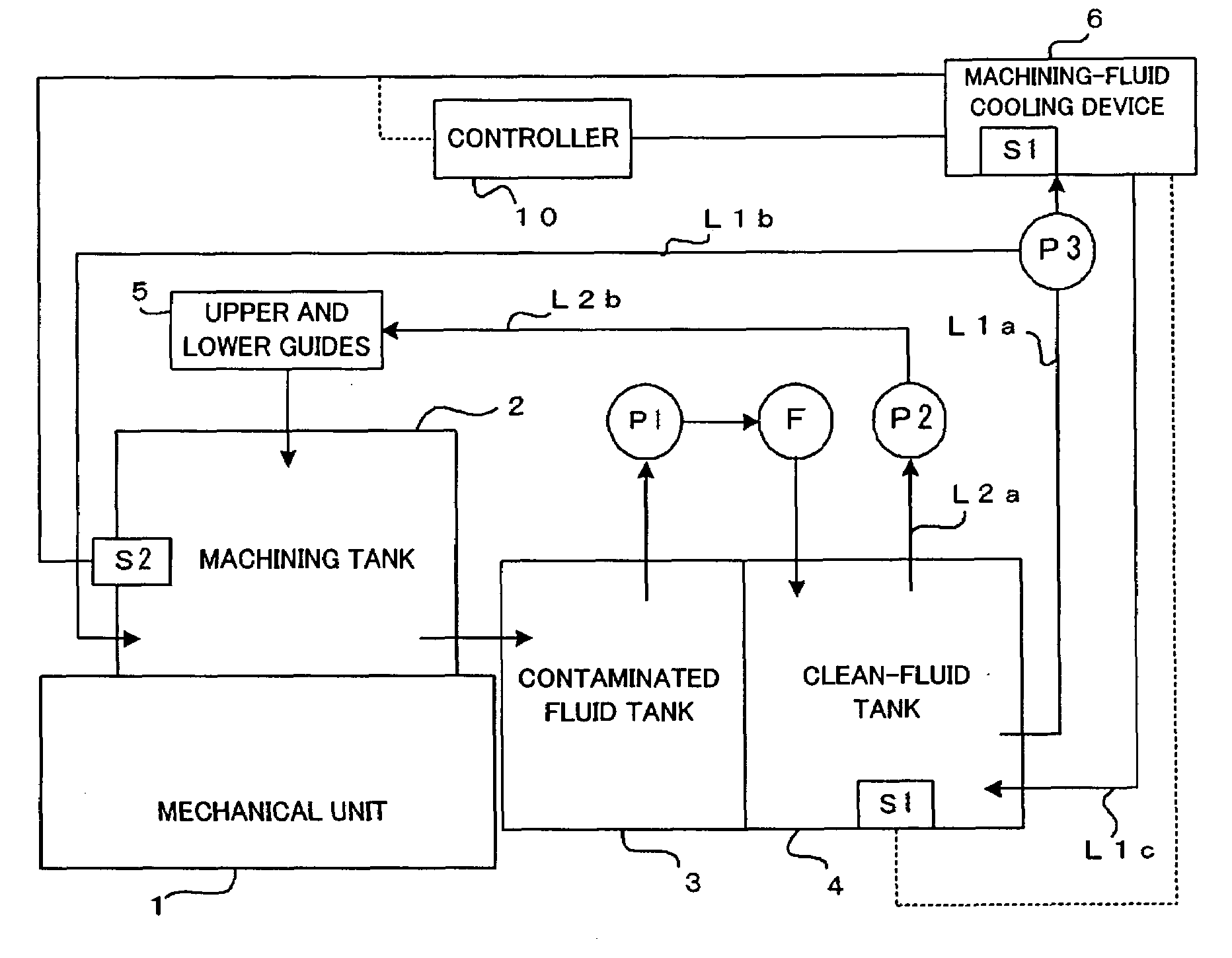
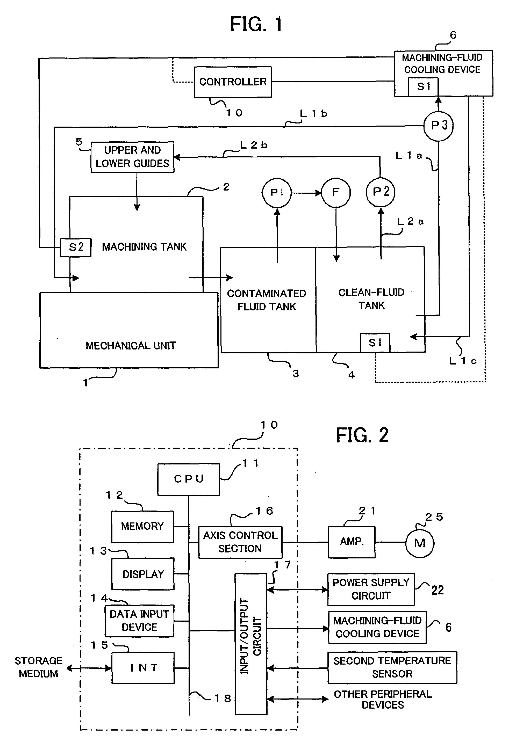
[0034]FIG. 1 is a schematic block diagram showing machining-fluid temperature control in an embodiment of the present invention. It is to be noted that the same elements as those in the conventional examples are denoted by the same reference signs.
[0035]Like the conventional examples, a machining tank 2 is fitted to a mechanical unit 1 of a wire electric discharge machine, and an electric discharge machining part is disposed within the machining tank 2. Specifically, a workpiece to be machined is mounted on and fitted to a table connected to the mechanical unit 1, and electric discharge machining is performed on the workpiece by producing electric discharges by applying a voltage between the workpiece and an wire electrode (not shown), while moving the workpiece relatively to the wire electrode. The machining fluid is supplied to and held in the machining tank 2. The machining fluid in the machining tank 2 contains swarf, etc. produced by electric discharges, and flows out to a cont...
PUM
| Property | Measurement | Unit |
|---|---|---|
| Temperature | aaaaa | aaaaa |
| Flow rate | aaaaa | aaaaa |
Abstract
Description
Claims
Application Information