Eureka AIR delivers breakthrough ideas for toughest innovation challenges, trusted by R&D personnel around the world.

Method for testing undercut on the inner diameter of pipe welds

a technology of pipe welds and undercuts, which is applied in the field of method for testing undercuts on the inner diameter of pipe welds, can solve the problems of increasing the frequency and degree of undercut of weld beads, affecting the quality of pipe welds, so as to reduce or eliminate the need for human inspection of undercuts

Inactive Publication Date: 2007-12-06
LINCOLN GLOBAL INC
View PDF6 Cites 71 Cited by
  • Summary
  • Abstract
  • Description
  • Claims
  • Application Information

AI Technical Summary

Benefits of technology

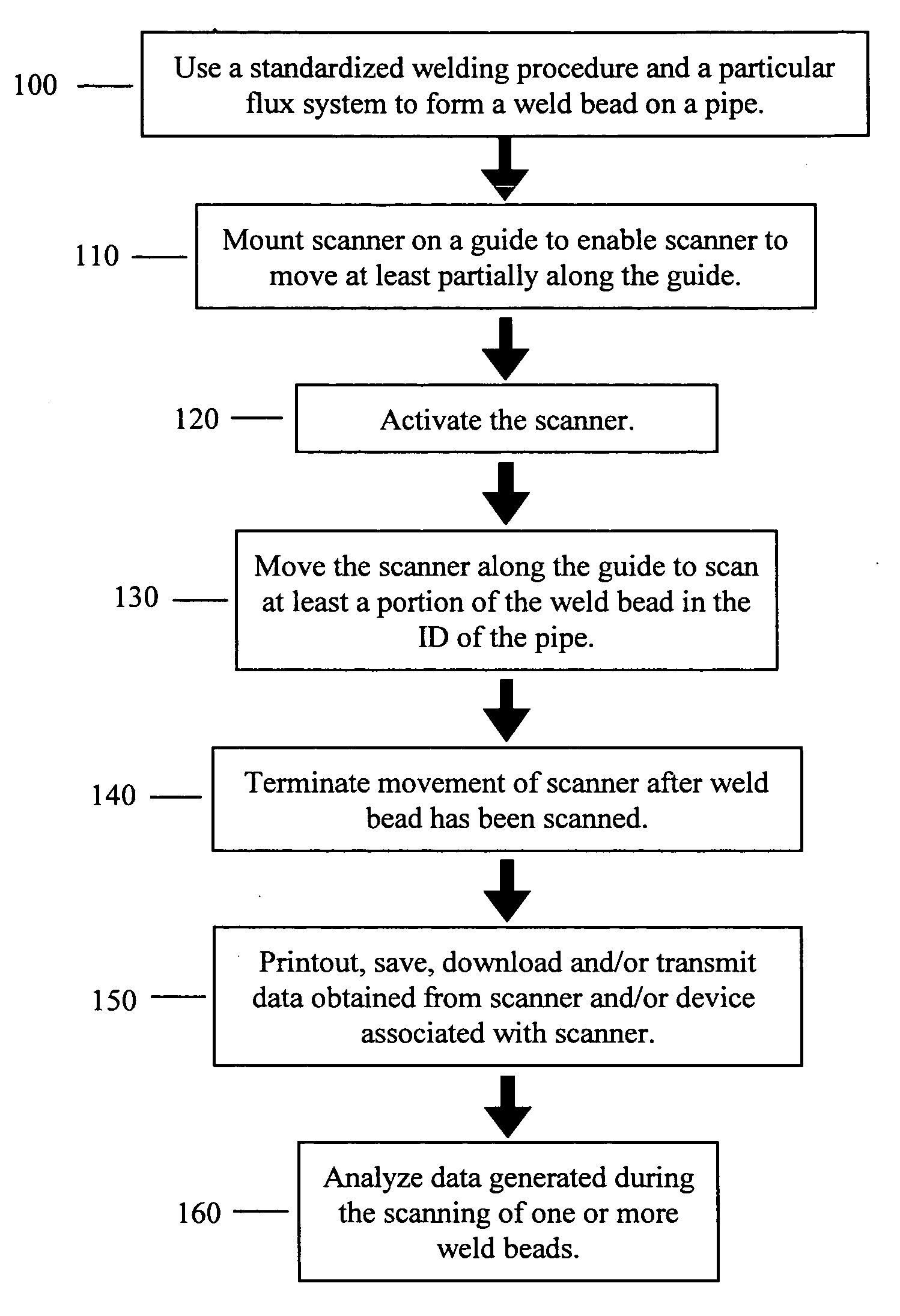
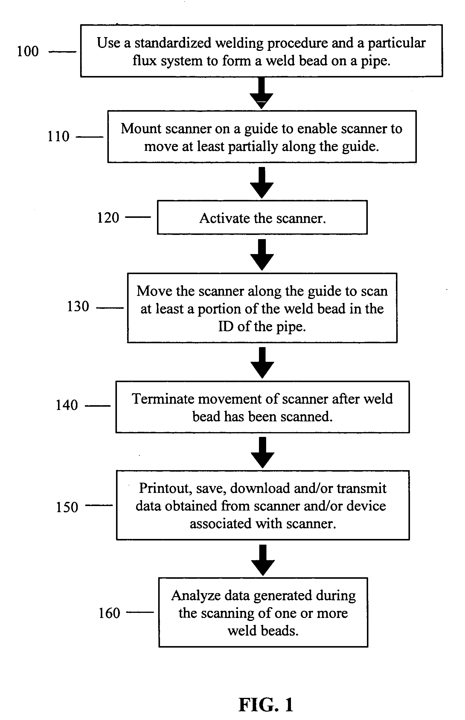
[0009]The welding procedure set forth above for use with an L-70 electrode which is provided by The Lincoln Electric Company is commonly used in various pipemills. As can be appreciated, other types and sizes of the consumable electrode can be used in accordance with this invention. The welding procedure uses appropriate levels of current and voltage when forming a pipe. The current decreases from the lead electrode (Arc 1) to the trailing electrode (Arc 3) and the voltage increases from the lead electrode (Arc 1) to the trailing electrode (Arc 3). In addition, the electrode angles for each electrode are not excessive.
[0039]Yet another and / or alternative non-limiting object of the present invention is the provision of a method and apparatus that can reduce or eliminate the need for human inspection of undercut.

Problems solved by technology

Undercut on the ID of the pipe is one of the most common types of defects experienced by pipe mills.
The existence of any degree of undercut can be considered a defect in the forming of a pipe.
Some types of undercut can be repaired by grinding out the region about the undercut; however, some undercut is so severe that the pipe has to be discarded or sold as a lesser grade pipe.
Attempted repair of the undercut of the weld bead on the ID of the pipe can be difficult and time consuming since such procedure involves the use of one or more individuals having to travel into the pipe to actually make the repair.
It has been found that different flux compositions can result in an increase or decrease in the frequency and degree of undercut of the weld bead on the ID of the pipe during the formation of a pipe.
These properties and / or others affect the quality of the weld bead and the occurrence of undercut of the weld bead on the ID of the pipe.
In view of the fact that the manual inspection of undercut is somewhat subjective and will vary based on the particular inspector, there has been some difficult in determining which flux system for a particular welding operation results in the least about of undercut.

Method used


Image

  • Method for testing undercut on the inner diameter of pipe welds
  • Method for testing undercut on the inner diameter of pipe welds
  • Method for testing undercut on the inner diameter of pipe welds

Examples


Embodiment Construction

[0045]The present invention is directed to an apparatus and method of analyzing a weld bead formed during the manufacture of pipe. The invention will be described with particular reference to analyzing a weld bead formed on pipe; however, it will be appreciated that the apparatus and method of the invention is not limited to analyzing a weld bead formed on pipes. The invention will also be described with particular reference to the detection of undercut about a formed weld bead; however, it will be appreciated that the method and apparatus can be used to analyze and / or detect other or additional features of a weld bead.

[0046]The method and apparatus of the present invention is particularly useful in evaluating the relative tendency of fluxes intended for use in pipe welding to exhibit undercut of the weld bead on the inner diameter (ID) of the pipe. The formation of undercut on the ID of the pipe results in a defective pipe weld. This defect must be repaired or the pipe will have to...


PUM

PropertyMeasurementUnit
Timeaaaaaaaaaa
Angleaaaaaaaaaa
Angleaaaaaaaaaa

Abstract

A method and apparatus of comparing two or more welding flux systems to determine which flux system results in the smallest incidence of undercut about a weld bead in an inner diameter of a pipe.

Description

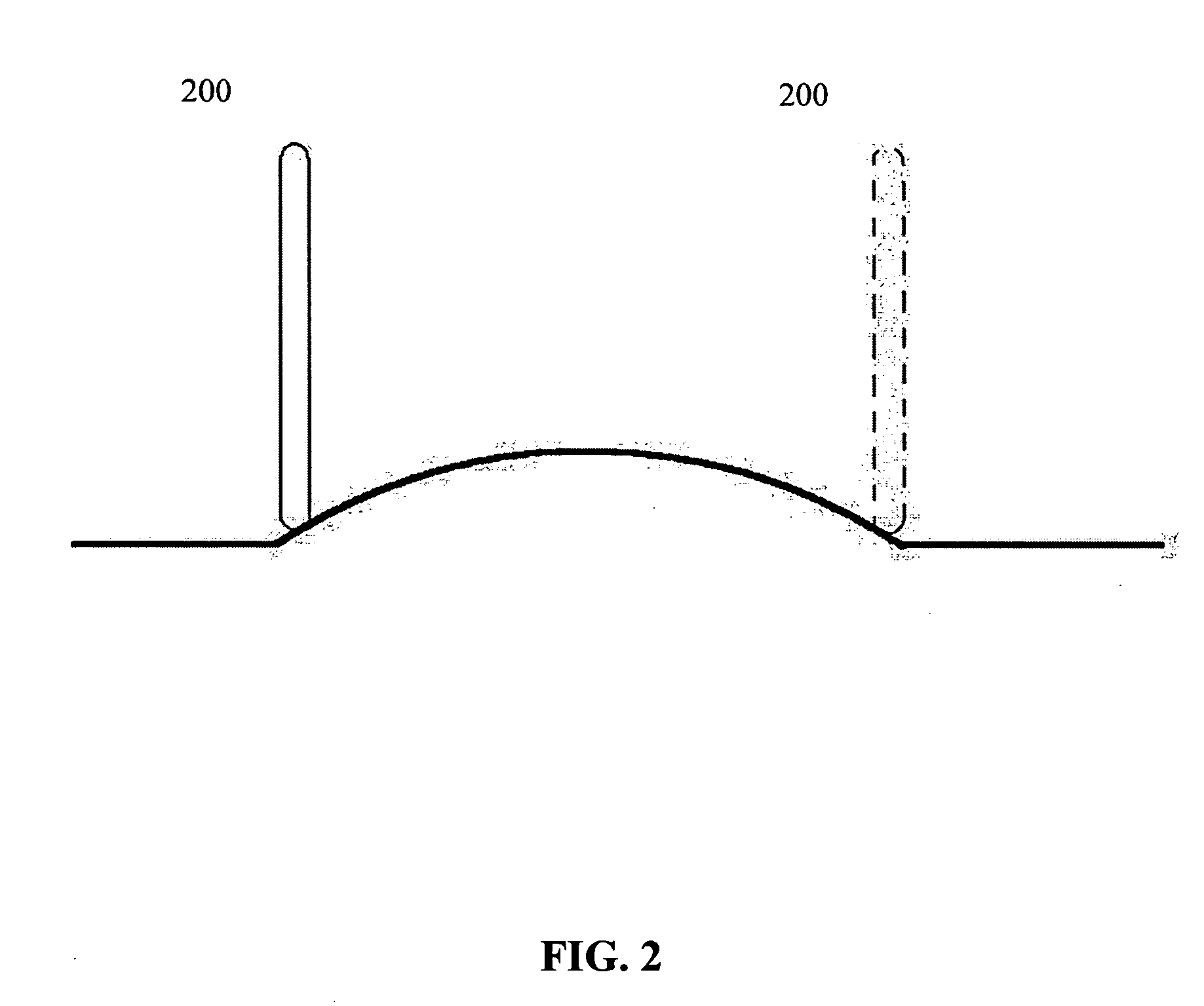
[0001]The invention is directed to the art of welding, more particularly to a test procedure for measuring the undercut of a weld bead, and even more particularly to a test procedure for measuring the undercut of a weld bead in a formed pipe.BACKGROUND OF THE INVENTION[0002]Large pipe sections are commonly formed by bending large sheets of metal together and then joining the edges of the metal sheet by use of a weld bead. The weld bead is commonly formed by a submerged arc welding process; however, other types of welding processes can be used. After the pipe has been formed, the interior of the pipe is inspected to determine the quality of the weld bead. One common problem encountered after the formation of the weld bead is undercut. Undercut can occur when the welding arcs melt away the edges of the metal sheet and the weld bead does not completely fill in this melted area, thereby leaving a notch or other depressed region between the weld metal and the edge of the metal sheet. The...

Claims


Application Information

Patent Timeline
IPC IPC(8): B23K9/095
CPCB23K2201/06B23K31/12B23K2101/06
Inventor JAMES, MATTHEW JAYCOYNE, PATRICK J.
Owner LINCOLN GLOBAL INC
Why Eureka
Eureka Blog
Learn More