High speed amplifier with controllable amplification and output impedance and comparator using the same

Inactive Publication Date: 2007-12-06
RENESAS ELECTRONICS CORP
View PDF9 Cites 8 Cited by
  • Summary
  • Abstract
  • Description
  • Claims
  • Application Information

AI Technical Summary

Benefits of technology

[0013] Further in a comparator including a plurality of first amplifiers of a two-input and two-output type connected in series and a second amplifier of a two-input and one-output type connected

Problems solved by technology

In the above-described second prior art comparator, however, since the OFF timings of the above-mentioned switches must be determined in view of the maximum values of delay time periods of the fast amplifiers, the stable time period is

Method used


Image

  • High speed amplifier with controllable amplification and output impedance and comparator using the same
  • High speed amplifier with controllable amplification and output impedance and comparator using the same
  • High speed amplifier with controllable amplification and output impedance and comparator using the same

Examples


Embodiment Construction

[0030] Before the description of the preferred embodiment, a prior art sequential successive approximation A / D converter and prior art comparators applied to the sequential successive approximation A / D converter will be explained with reference to FIGS. 1 to 7.

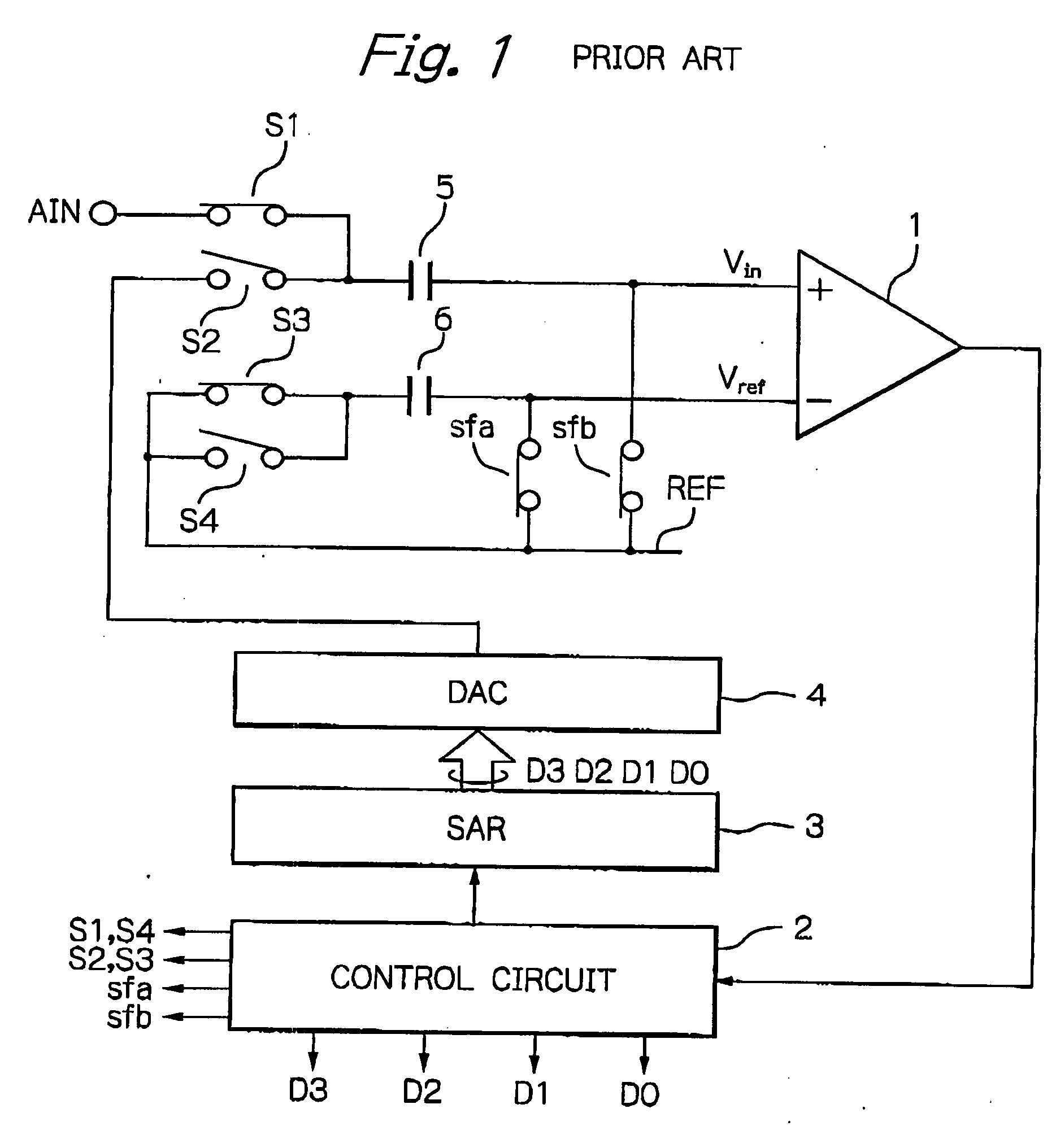
[0031] In FIG. 1, which illustrates a prior art sequential successive approximation A / D converter, a comparator 1 compares an input voltage Vin with a reference voltage Vref to generate an output voltage Vout. A control circuit receives the output signal of the comparator 1 to control a content of a sequential approximation register (SAR) 3. A digital-to-analog (D / A) converter 4 performs a D / A conversion upon the content of the sequential approximation register 3 to generate the input voltage Vin.

[0032] On the other hand, an end of an input capacitor 5 is connected to a positive input of the comparator 1, and an end of a reference capacitor 6 is connected to a negative input of the comparator 1. In this case, the capacitance...


PUM


Abstract

In an amplifier including first and second power supply terminals, first and second output terminals, a first load connected between the first power supply terminal and the first output terminal, a second load connected between the first power supply terminal and the second output terminal, a constant current source connected to the second power supply terminal, a first transistor connected between the first output terminal and the constant current source, a control terminal of the first transistor being adapted to receive an input voltage, and a second transistor connected between the second output terminal and the constant current source, a control terminal of the second transistor being adapted to receive a reference voltage, an amplification and output impedance switching circuit is connected between the first and second output terminals, so that the amplifier and output impedance switching circuit controls an amplification and output impedance of the amplifier in accordance with a control signal.

Description

BACKGROUND OF THE INVENTION [0001] 1. Field of the Invention [0002] The present invention relates to a high speed amplifier and a comparator using the same applied to a sequential successive approximation analog-to-digital (A / D) converter. [0003] 2. Description of the Related Art [0004] Generally, A / D converters are required to accurately convert an analog signal into a digital signal at high speed. [0005] One typical A / D converter is a sequential successive approximation A / D converter which is constructed by a comparator for comparing an input voltage with a reference voltage derived from an input analog voltage, a sequential approximation register (SAR), a digital-to-analog (D / A) converter for performing a D / A conversion upon the content of the sequential approximation register to generate the input voltage, and a control circuit for controlling the content of the sequential approximation register in accordance with the output signal of the comparator. This will be explained later...

Claims


Application Information

Patent Timeline
IPC IPC(8): H03F3/45H03F1/00
CPCH03F2203/45616H03F2203/45641H03F2203/45642H03F2203/45652H03F2203/45686H03F2203/45418H03F3/45475H03F2200/54H03F2200/78H03F2203/45138H03F2203/45171H03F3/45183
Inventor FURUTA, ATSUSHI
Owner RENESAS ELECTRONICS CORP
Why Eureka
Try Eureka