RF telemetry for an active medical device such as an implant or programmer for an implant

a medical device and telemetry technology, applied in the direction of piezoelectric/electrostrictive/magnetostrictive devices, electrical apparatus, impedence networks, etc., can solve the problems of affecting the sensitivity of the telemetry receiver, presenting a very abrupt band rejection characteristic, and advanced downsizing of electronic circuits

Active Publication Date: 2007-12-06
SORIN CRM
View PDF14 Cites 18 Cited by
  • Summary
  • Abstract
  • Description
  • Claims
  • Application Information

AI Technical Summary

Benefits of technology

[0017] The purpose of this invention is preferably to realize such a device and / or programmer, the RF circuits of which present the following advantages:
[0019] a potentially integrable filter, so as to obtain a monolithic component including the RF transmitter / receiver chip along with its associated band rejection filter. Such an integration presents many advantages: the overall cost reduction, reduction of insertion losses and maximization of the useful area (so as to miniaturize implants, it is known, nowadays, to stack many monolithic chips with one on top of the others);
[0021] reduction of parasite impedances, notably inductances (conductors, conductive pathways, bondings, etc.), allowing to reduce the insertion losses and prevent from having to retune the filter after the integration or bonding on the circuit;

Problems solved by technology

RF telemetry circuits therefore require the use of very efficient band-pass filters, presenting a very abrupt band rejection characteristic.
This shortcoming is particularly embarrassing when it comes to implanted devices, which, as it can be easily understood, require an advanced downsizing of electronic circuits, due to the small available space within their cases.
Also, from a technological point of view, these SAW resonators are only available as discrete components that must be bonded onto the electronic circuit of the implant, with consequent shortcomings, notable in terms of additional steps as part of manufacturing processes and a higher cost.
Finally, from the electrical point of view, SAW resonators present an excellent selectivity, but introduce significant insertion losses in the circuits in which they are used, consequently affecting the sensitivity of the telemetry receiver.
However, these FBAR resonators are more difficult to make, for they require micro-machining of a very thin movable membrane, likely to become resonant (one will describe more in details the structure of FBAR resonators by reference to FIGS. 2a and 2b).
That micro-machining is difficult to implement, notably as part of a collective process, which introduces much scrap during manufacturing of the components.
From an industrial point of view, though it is theoretically possible to integrate the FBAR resonator along the manufacturing process of the circuit it is associated with, such an integration is practically difficult to implement with a satisfactory yield, which is the reason why the FBAR resonators available nowadays are only available in the form of discrete components.
The FBAR component must therefore be bonded onto the electronic circuit or onto the hybrid board through an additional process such as wire-bonding or flip-chip, which, similarly to the case of SAW resonators, dramatically increases manufacturing cost and reduces electrical performances due to the presence of wires, conductive pathways, etc.
Apart from the difficulty to find and sustain the tuning of an FBAR resonator, this latter presents a rejection characteristic less abrupt than that of a SAW resonator.
Such a multiplication of components consequently increases cost, volume and difficulties for developing the final circuit.

Method used


Image

  • RF telemetry for an active medical device such as an implant or programmer for an implant
  • RF telemetry for an active medical device such as an implant or programmer for an implant
  • RF telemetry for an active medical device such as an implant or programmer for an implant

Examples


Embodiment Construction

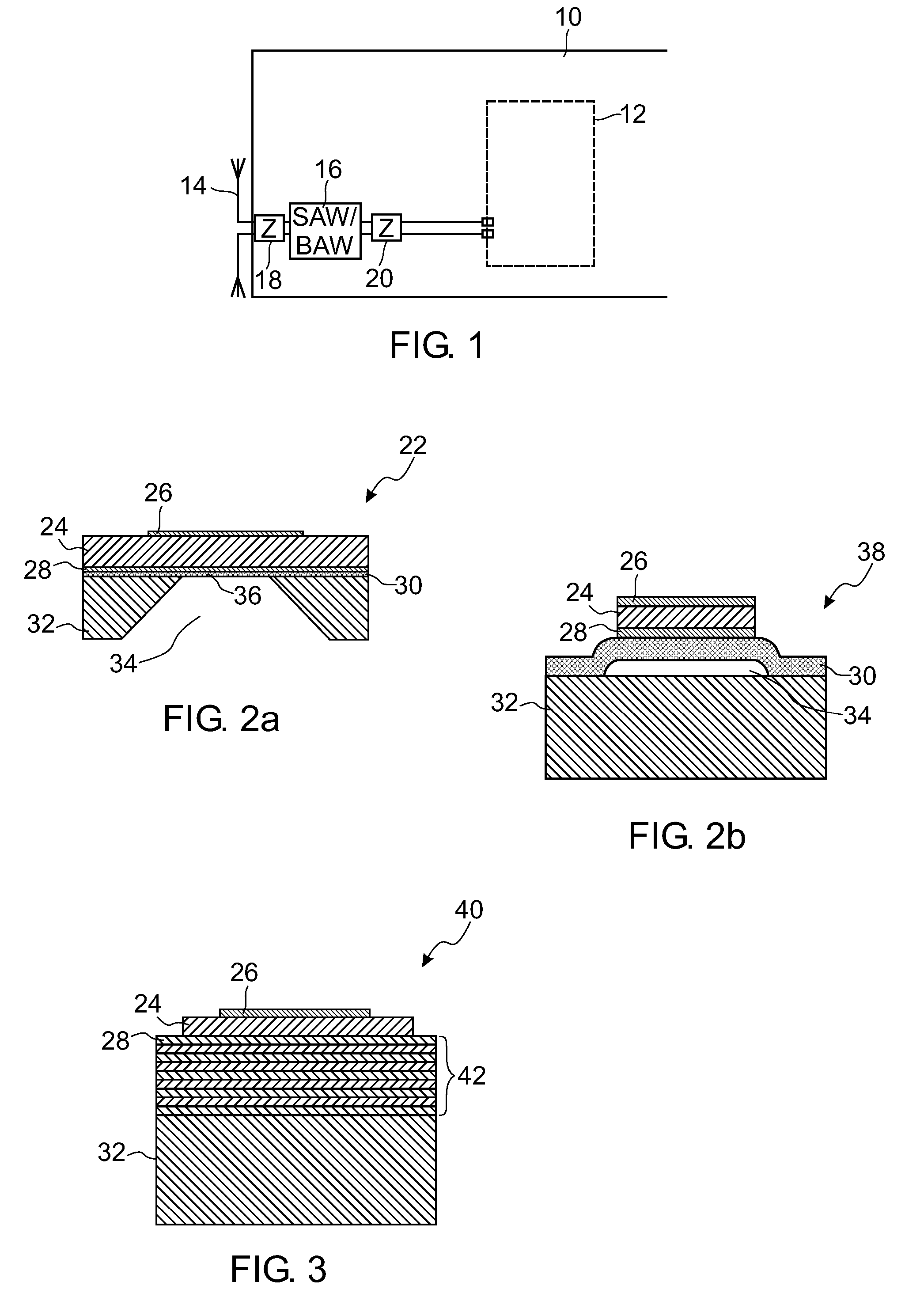
[0046] With reference to FIG. 1, a schematic representation of the configuration of a RF telemetry circuit of an active medical device following the prior art is shown.

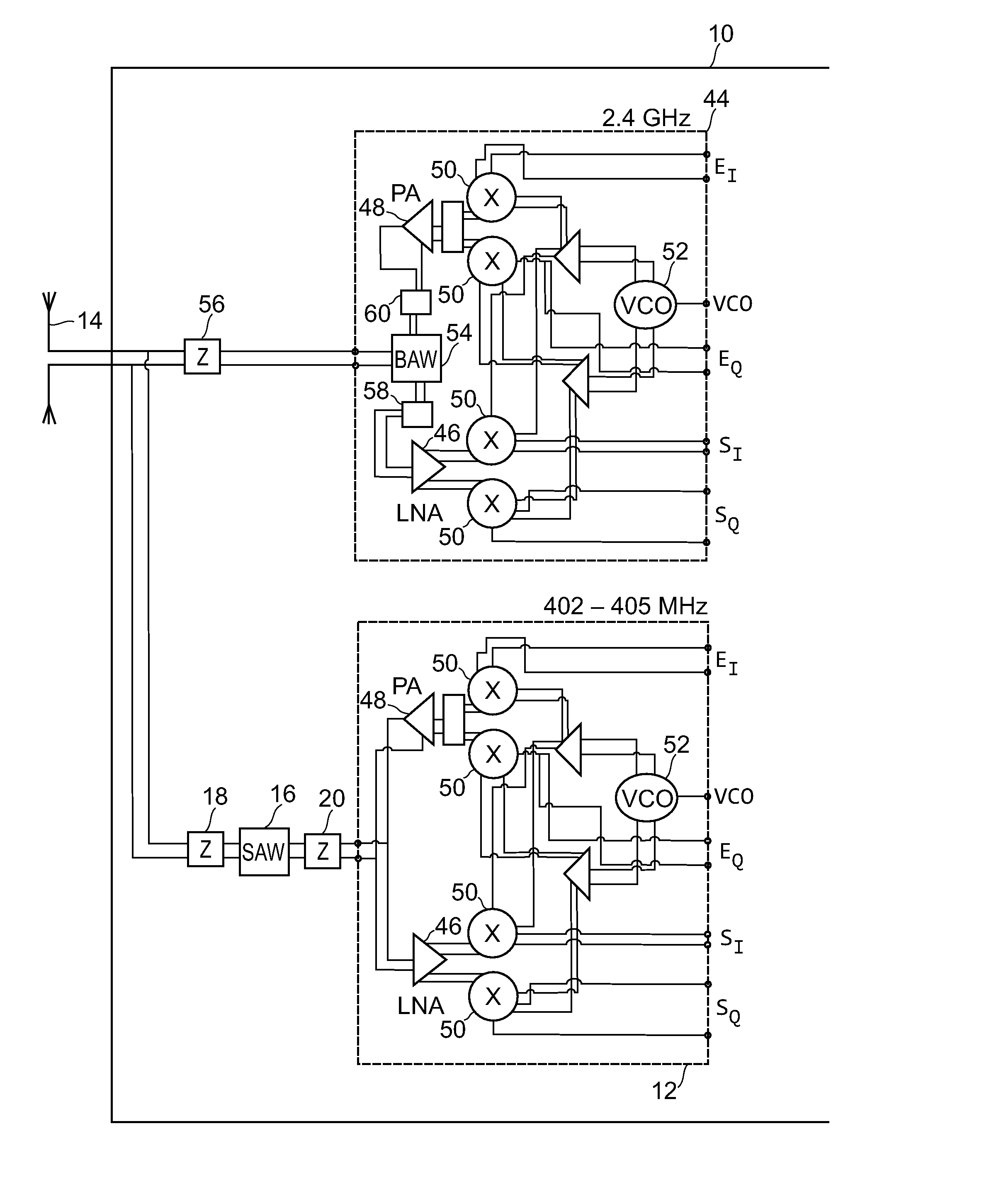
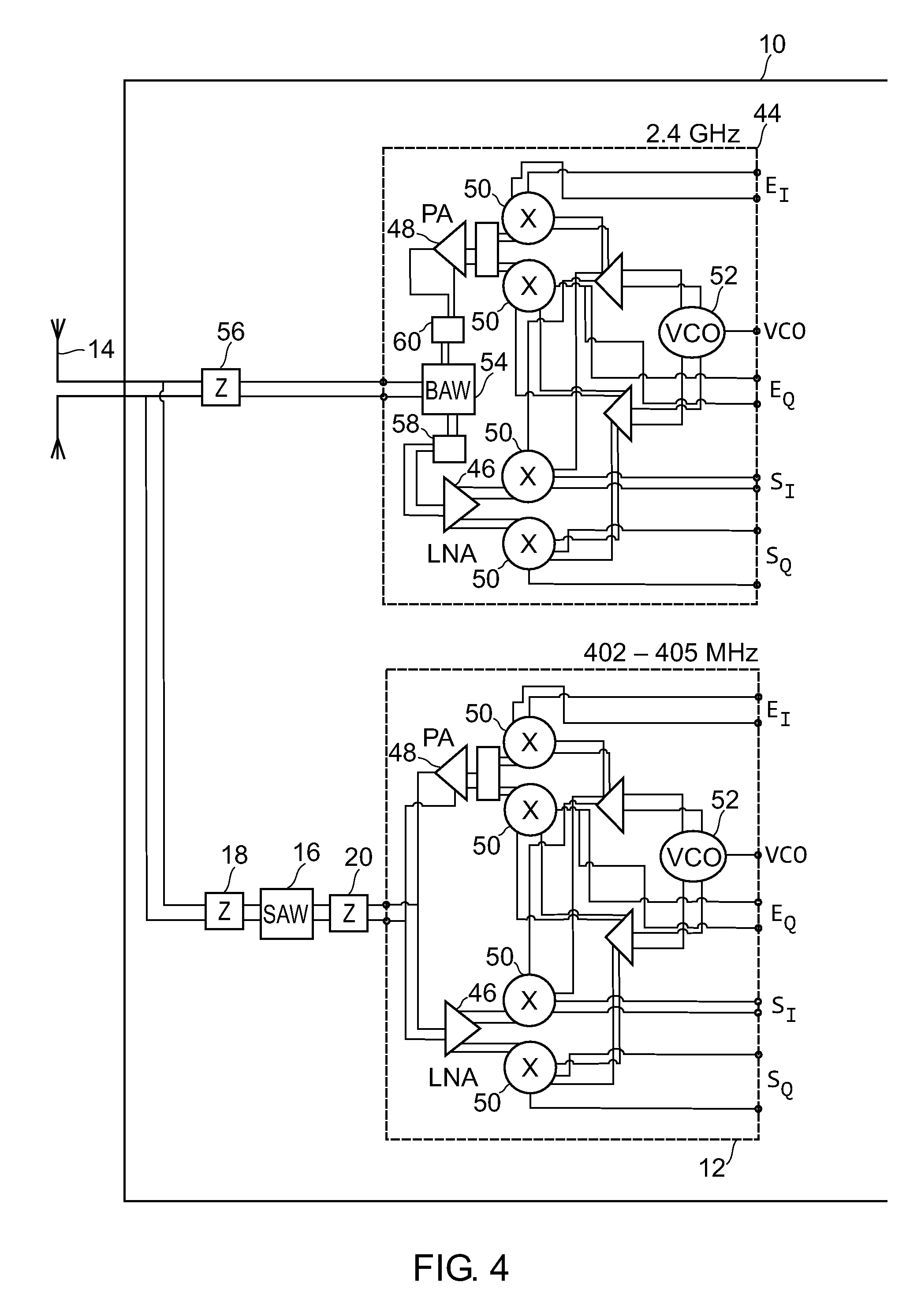
[0047] Main circuit 10, typically realized on a hybrid substrate, comprises an RF telemetry transmitter / receiver 12 coupled to an antenna 14 incorporated in the device (for example, in the area of the implant connector head).

[0048] The rejection of parasite signals is ensured by interposing, between the antenna 14 and circuits 12, a resonator 16 such as a surface acoustic wave SAW resonator, or volume acoustic wave BAW resonator 16. Components for impedance matching 18, 20 are included, as needed, in order to ensure coupling and potential symmetrization, as well as reduce the insertion losses.

[0049] When the rejection filters of RF telemetry circuits of known implants implement BAW resonators, such resonators are components of the FBAR type presenting one of the two structures shown in FIGS. 2a and 2b. In the first...


PUM


Abstract

RF telemetry for an active medical device such as active implant or programmer for such implant. The device includes at least one RF antenna (14), and at least one RF telemetry transmitter / receiver (44) with, for coupling to the antenna, an associated band rejection filter (54). The band rejection filter (54) comprises at least one volume acoustic wave BAW resonator (40) of the SMR type with insulation by Bragg acoustic reflector (42). The device can be a multi-band device comprising a plurality of RF transmitters / receivers (12, 44) operating in respective distinct bands of frequencies such as the 402˜405-MHz, 863˜870-MHz, 902˜928-MHz and 2.4-GHz bands or by UWB transmission.

Description

[0001] The present invention relates to an active medical device as such devices are defined by the Jun. 14, 1993 93 / 42 / CE directive of the Counsel of European Communities, and more particularly to active implantable medical devices as such devices are defined by the Jun. 20, 1990 90 / 385 / CEE directive of the Counsel of European Communities. [0002] These devices include devices that are intended to monitor cardiac activity and generate pulses for pacing, resynchronization, defibrillation and / or cardioversion in response to a rhythm disorder detected by the device. It also includes neurologic devices, pumps for the diffusion of medical substances, cochlear implants, implanted biological sensors, etc., as well as devices for pH measurement or intracorporal impedance measurement (such as the measurement of transpulmonary or intracardiac impedance). One will also note that, although this invention is particularly advantageous for implementation in implanted devices, such as pacemakers, c...

Claims


Application Information

Patent Timeline
IPC IPC(8): H03H9/70H03H9/58
CPCA61N1/37223H03H9/175A61N1/37276
Inventor DAL MOLIN, RENZO
Owner SORIN CRM
Why Eureka
Try Eureka