Heat-Dissipating Structure For Lamp

a technology of heat dissipation structure and led lamp, which is applied in the direction of lighting, heating apparatus, cooling/ventilation/heating modifications, etc., can solve the problems of inconvenient gripping of heat-dissipating bodies, and insufficient heat generation of light-emitting diodes, so as to facilitate gripping, enhance convenience and comfort in use, and increase the area for heat dissip

Inactive Publication Date: 2007-12-06
JAFFE
View PDF9 Cites 108 Cited by
  • Summary
  • Abstract
  • Description
  • Claims
  • Application Information

AI Technical Summary

Benefits of technology

[0009]In view of the above drawback, the present invention is to provide a heat-dissipating structure for a lamp, which has two cylinders. The heat-dissipating body is designed to have a cylindrical structure to not only increase the area for heat dissipation but also facilitate the user to grip the heat-dissipating body in assembling or conveying the lamp, thereby to enhance the convenience and comfortable feeling in using.
[0010]The present invention provides a heat-dissipating structure for a lamp, which comprises a heat-dissipating body and a heat pipe. The heat-dissipating body includes a first cylinder and a second cylinder provided within the first cylinder. A plurality of heat-dissipating pieces i

Problems solved by technology

At earlier stage, the intensity of the light-emitting diodes are insufficient, however, the recent development of the LED has made a great advance in their intensity.
Especially, with the development of high-power light-emitting diodes, their material needs to consume larger amount of electric current, and thus generates more heat.
Although such arrangement of the heat-di

Method used


Image

  • Heat-Dissipating Structure For Lamp
  • Heat-Dissipating Structure For Lamp
  • Heat-Dissipating Structure For Lamp

Examples


Embodiment Construction

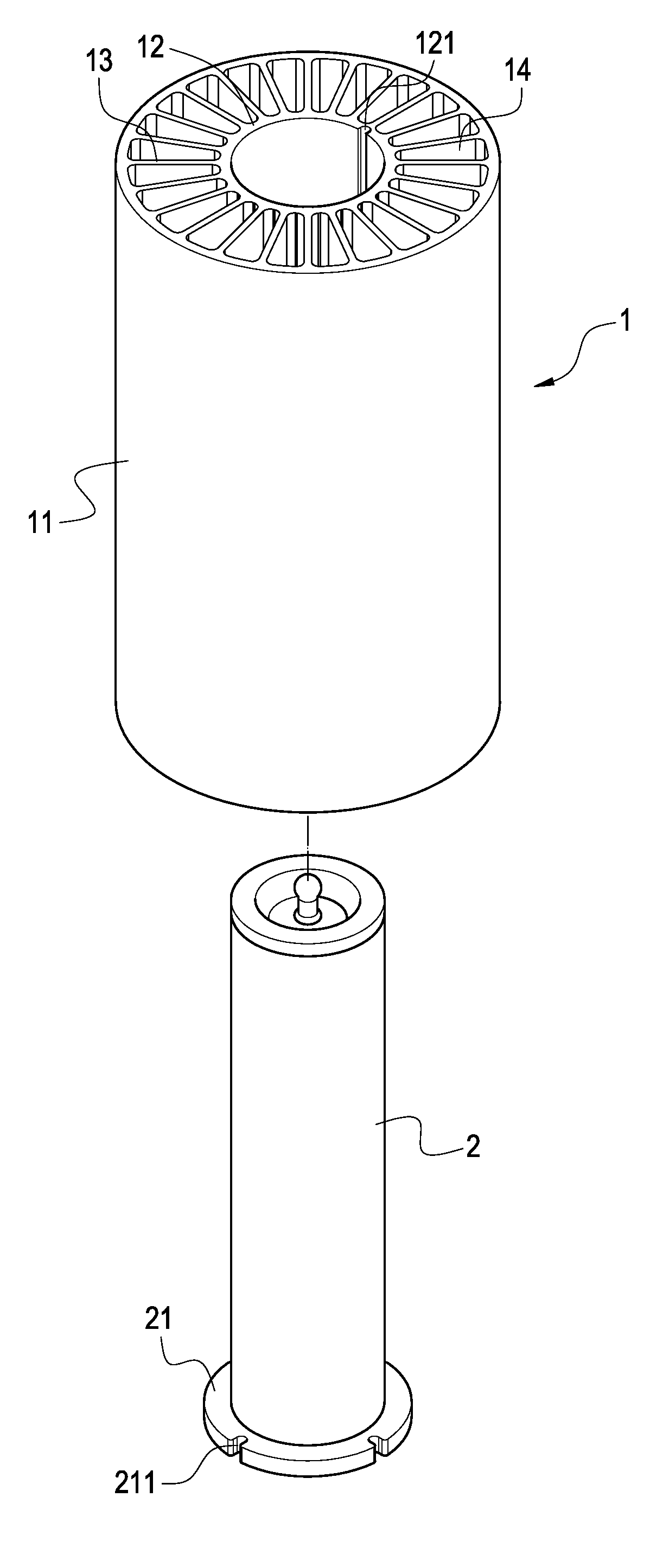
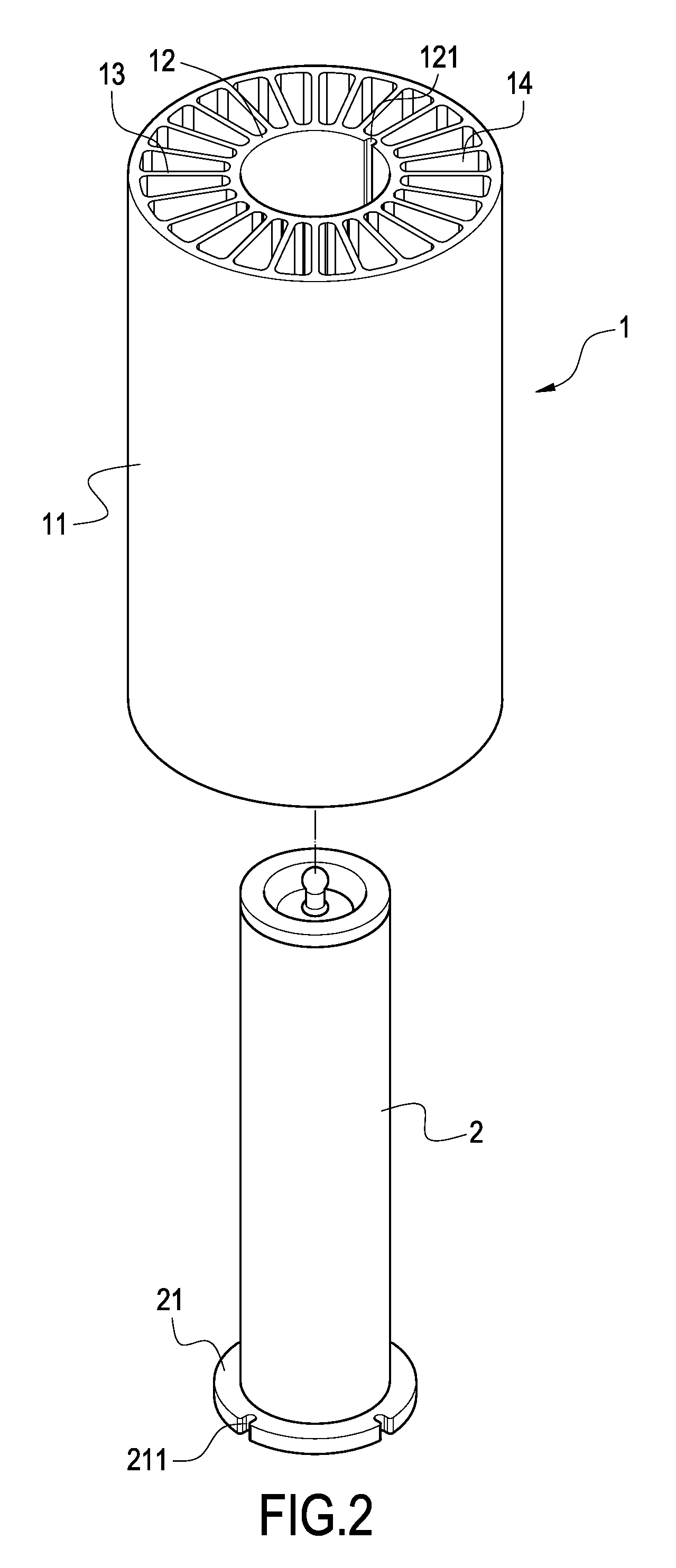
[0019]With reference to FIG. 2, it is an exploded perspective view showing the structure of the present invention. It can be seen from the drawing that the heat-dissipating structure of the present invention mainly comprises a heat-dissipating body 1 and at least one heat pipe 2. The heat-dissipating body is made of materials having high heat conductivity. The heat-dissipating body further comprises a first cylinder 11 and at least a second cylinder 12 (one shown in the drawing). The cross section of the first cylinder 11 is formed into a circular shape. The second cylinder 12 is provided within the first cylinder 11 for accommodating the heat pipe 2. A plurality of heat-dissipating pieces 3 is connected between the first cylinder 11 and the second cylinder 12. As seen from the top, the plurality of heat-dissipating pieces 13 is formed into a radial arrangement. Further, a heat-dissipating path 14 is formed between each heat-dissipating piece 13 for allowing the air to flow therein....


PUM


Abstract

A heat-dissipating structure includes a heat-dissipating body and a heat pipe. The heat-dissipating body includes a first cylinder and a second cylinder provided within the first cylinder. A plurality of heat-dissipating pieces is further connected between the first cylinder and the second cylinder. A heat-dissipating path is formed between each heat-dissipating piece. The heat pipe is accommodated in the second cylinder and tightly connected thereto. With the heat conduction of the heat pipe, the heat generated by the operation of the LED lamp is absorbed and conducted to the second cylinder. Then, the heat is dissipated uniformly to the plurality of heat-dissipating pieces and the first cylinder. With the above arrangement, the present invention achieves the desired heat-dissipating effect and it is easy to grip and assemble the heat-dissipating body.

Description

BACKGROUND OF THE INVENTION[0001]1. Field of the Invention[0002]The present invention relates to a heat-dissipating structure, and in particular to a heat-dissipating structure suitable for a LED lamp.[0003]2. Description of Prior Art[0004]With the development of novel materials and techniques, light-emitting diodes (LED) have been widely used in various kinds of fields because they are compact in size, short in response time and do not generate any pollution. At earlier stage, the intensity of the light-emitting diodes are insufficient, however, the recent development of the LED has made a great advance in their intensity. Therefore, the LEDs tend to replace the conventional illuminating elements.[0005]Especially, with the development of high-power light-emitting diodes, their material needs to consume larger amount of electric current, and thus generates more heat. In order to make the illuminating device having light-emitting diodes to operate under a suitable working temperature...

Claims


Application Information

Patent Timeline
IPC IPC(8): H05K7/20
CPCF21V29/004F21Y2101/02F21V29/006F21V29/83F21V29/75F21V29/773F21V29/677F21V29/51F21Y2115/10
Inventor LI, JIA-HAO
Owner JAFFE
Why Eureka
Try Eureka