Compound Lens Having a Sealing Configuration Suitable For Motor Vehicles

a technology of compound lens and sealing configuration, which is applied in the direction of mountings, instruments, data recording, etc., can solve the problems of dew formation in the optical path, degradation of image quality, and high mechanical stress on the camera module used in the operation of the motor vehicle, so as to achieve cost-effective assembly and precise setting of nominal clearance

Inactive Publication Date: 2007-12-06
ROBERT BOSCH GMBH
View PDF15 Cites 14 Cited by
  • Summary
  • Abstract
  • Description
  • Claims
  • Application Information

AI Technical Summary

Benefits of technology

[0005] The compound lens design according to the present invention for an optical recording device makes it possible for individual parts to be assembled cost-effectively, including a front lens that is to be inserted imperviously, even while allowing for the typical manufacturing tolerances inherent in the mechanical dimensions of the individual parts. The present invention provides for a spacer ring to be integrated in the lens stack in such a way that it is set in, between the front lens and the second lens positioned downstream thereof. Along with the spacer rings, a sealing ring is inserted, making it possible to achieve both a defined compression for sealing off two surfaces, as well as a precise setting of the nominal clearance between the lenses within the lens stack.

Problems solved by technology

Camera modules used in motor vehicle operation are not only subject to high mechanical stresses, but to considerable temperature fluctuations as well, and to the effects of moisture.
When a camera module is used that does not have a completely impervious design, under the climatic conditions typical of automotive applications, this can lead, on the one hand, to dew formation in the optical path and, on the other hand, to degradation of the image quality.
Because manufacturing variances are inherent in the structural heights within a lens stack which may include a plurality of lenses, a constant compression is not ensured for all pieces when a sealing ring is clamped between the frontmost lens surface and a contact mass, such as a ring-shaped area in the tubular housing of the compound lens.
Moreover, it must be ensured that the sealing ring is not unevenly clamped, which can result, for example, from localized overstraining when the parts are screwed in place during assembly.
When a seal rests on a front surface, any encroachment on the available beam diameter is disadvantageous, since the edge thickness of the front lens cannot be arbitrarily reduced.

Method used


Image

  • Compound Lens Having a Sealing Configuration Suitable For Motor Vehicles
  • Compound Lens Having a Sealing Configuration Suitable For Motor Vehicles
  • Compound Lens Having a Sealing Configuration Suitable For Motor Vehicles

Examples


Embodiment Construction

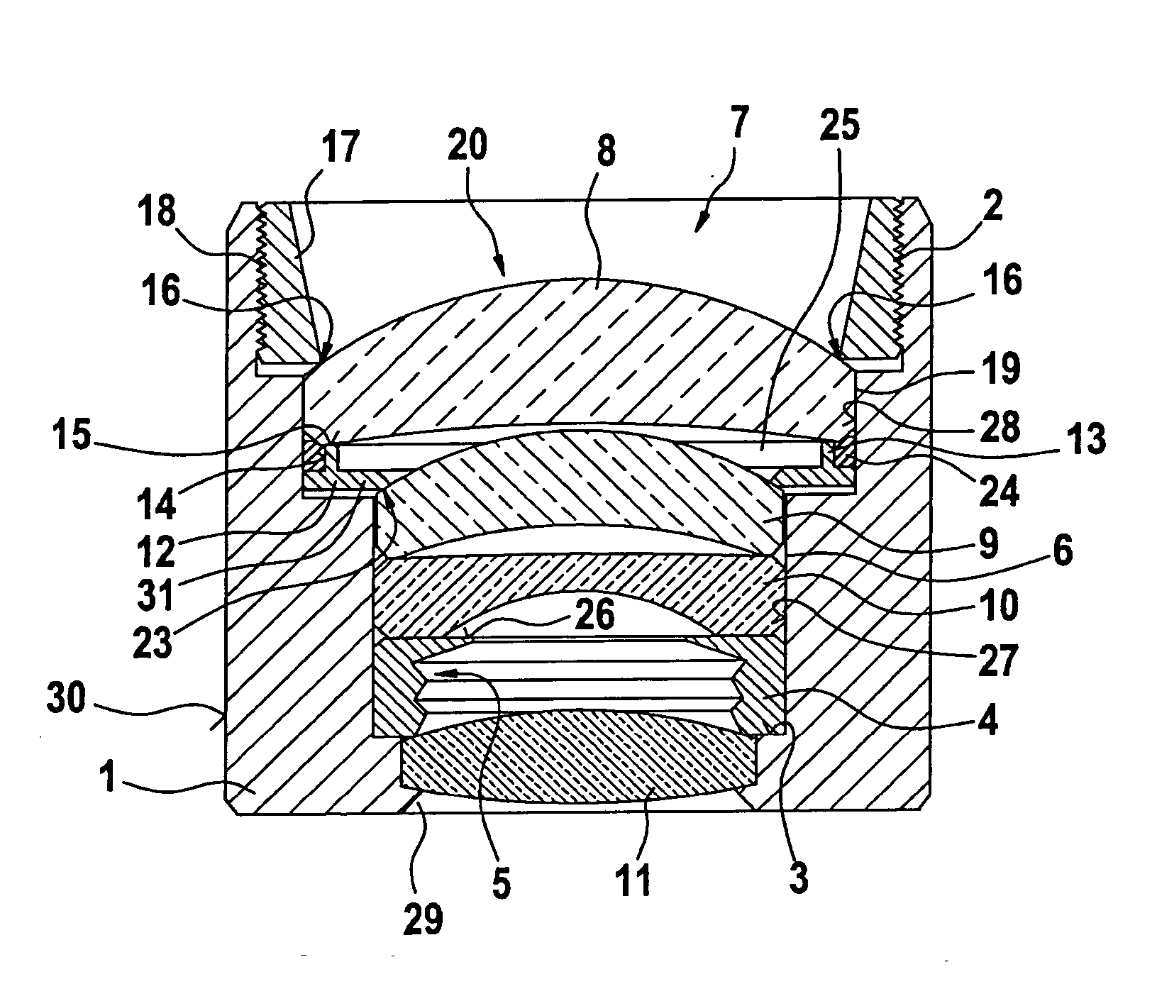
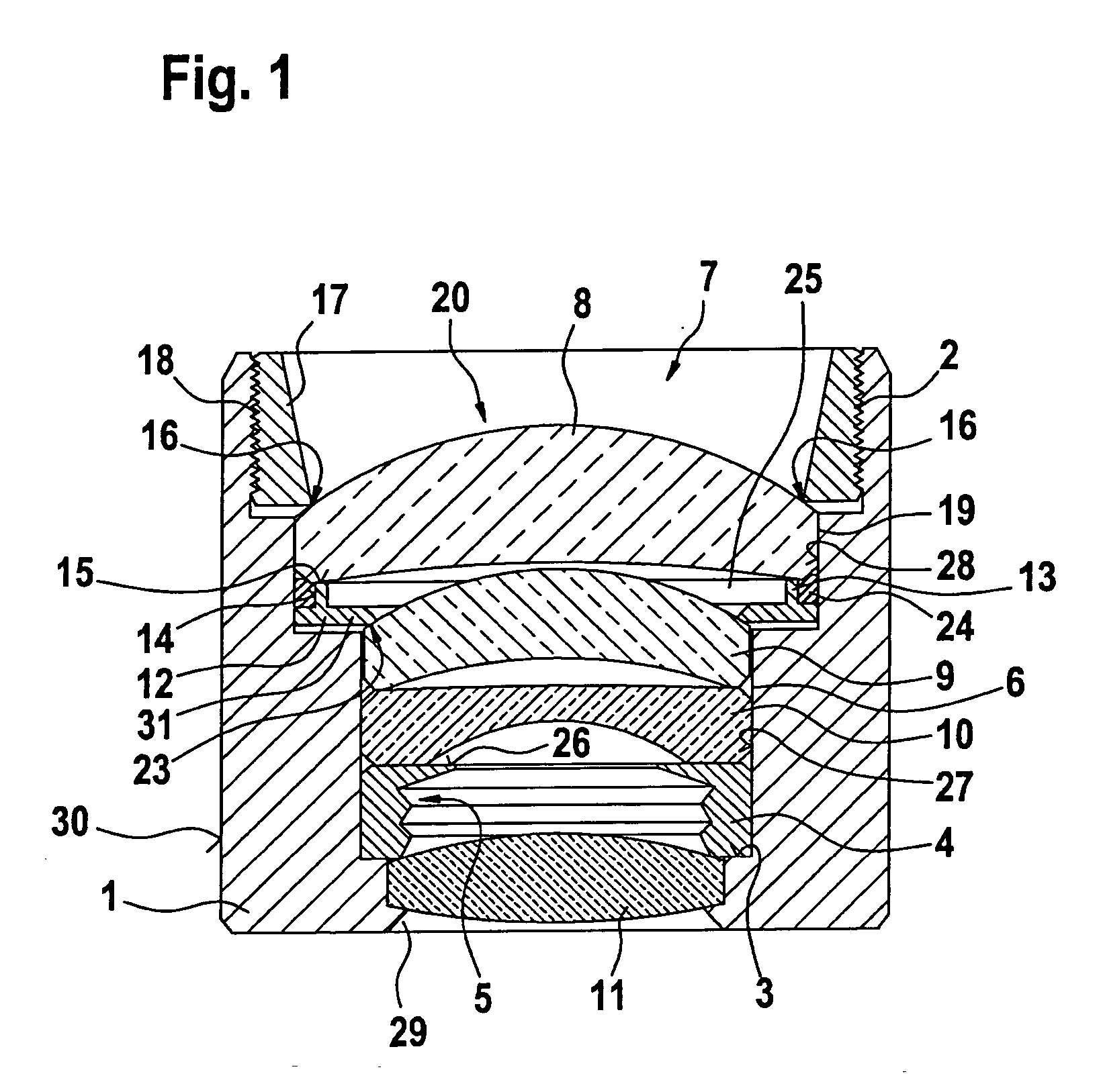
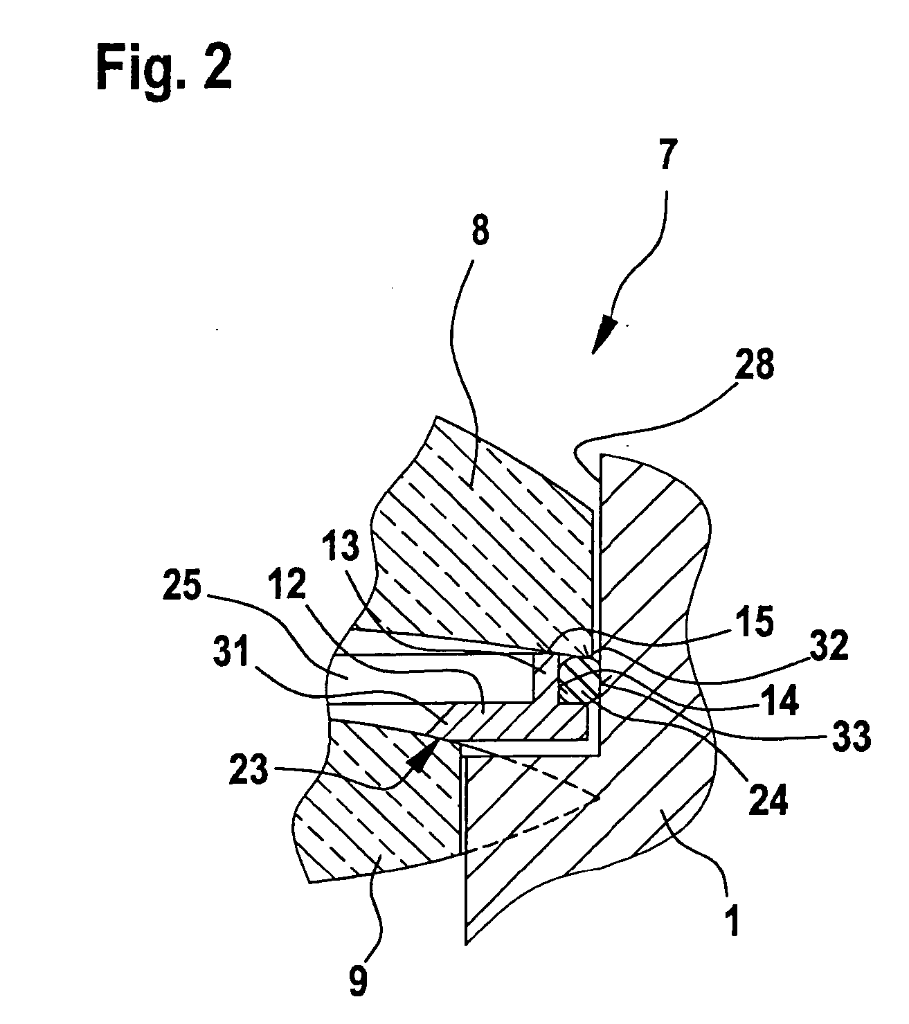
[0012]FIG. 1 shows a compound lens in whose tubular housing 1 a lens stack 7 is inset. Tubular housing 1 includes a threaded section 2, in which a securing ring 17 is screwed into position. Securing ring 17 includes an external thread 18 which is complementary to threaded section 2 and which fixes a first lens 8 (front lens) of lens stack 7 in position in tubular housing 1. Lens stack 7, which is accommodated in tubular housing 1, encompasses first lens 8 (front lens) already mentioned, a subjacent second lens 9, another third lens 10, as well as a fourth lens 11.

[0013] Hermetically closing an aperture 29 is fourth lens 11, which is inset at the bottom of tubular housing 1. Located above fourth lens 11 is a diaphragm ring 4, which may have a shaping 5 adapted to the particular optical application. On its upper side, diaphragm ring 4 has a plane face 26, on which a third lens 10 rests flat. A second, convexly and concavely curved lens 9 rests on third lens 10. Second lens 9 and thir...


PUM

PropertyMeasurementUnit
resilient sectionaaaaaaaaaa
mechanical stressesaaaaaaaaaa
temperatureaaaaaaaaaa

Abstract

An optical recording unit having a compound lens which includes a lens stack. The lens stack encompasses a plurality of lenses, which are inset in a tubular housing. The lens stack includes a spacer ring which accommodates a sealing material or a sealing element and which is braced resiliently against one of the lenses in the tubular housing.

Description

BACKGROUND INFORMATION [0001] Camera modules used in motor vehicle operation are not only subject to high mechanical stresses, but to considerable temperature fluctuations as well, and to the effects of moisture. When a camera module is used that does not have a completely impervious design, under the climatic conditions typical of automotive applications, this can lead, on the one hand, to dew formation in the optical path and, on the other hand, to degradation of the image quality. Moisture condensation is often observed when a high relative air humidity has set in inside of the camera module for a length of time at elevated temperatures, and the camera module is then cooled within a short period of time. [0002] Optical recording units constructed from a compound lens and a sensor chip are typically designed to be hermetically sealed. The ingress of moisture resulting from vapor permeability that may be excessive for many of the materials used, can be controlled by using absorbing...

Claims


Application Information

Patent Timeline
Patent Type & Authority Applications(United States)
IPC IPC(8): G11B7/00G02B7/02
CPCG02B7/026
Inventor APEL, UWEHOELLT, CHRISTIAN
Owner ROBERT BOSCH GMBH
Why Eureka
Try Eureka