Method and Apparatus for Medical X-radiography

Active Publication Date: 2007-12-06
PALODEX GROUP
View PDF4 Cites 22 Cited by
  • Summary
  • Abstract
  • Description
  • Claims
  • Application Information

AI Technical Summary

Benefits of technology

[0007]The invention relates also to an X-ray imaging apparatus for eliminating error elements resulting from movements of an imaged object in X-radiography, comprising imaging means for performing X-radiography on an imaged object for compiling three-dimensional X-radiographic information. The X-ray imaging apparatus comprises means for creating a model geometry of an X-ray imaging process, said creation work comprising a determination of the location for two or more position markers in a set of coordinates graded for the X-ray imaging apparatus, means for working out predictions regarding the locations of position markers during X-radiography, and means for defining projected or most likely locations for position markers on the basis of determined l

Problems solved by technology

One of the most serious sources of error in three-dimensional medical X-radiography results from movements of a patient during the imaging session.
This source of error, even if an X-ray image may not be totally ruined thereby, results in X-ray images which are more blurred, thereby leading to uncertain interpretations and, in a worst ca

Method used


Image

  • Method and Apparatus for Medical X-radiography
  • Method and Apparatus for Medical X-radiography
  • Method and Apparatus for Medical X-radiography

Examples


Example

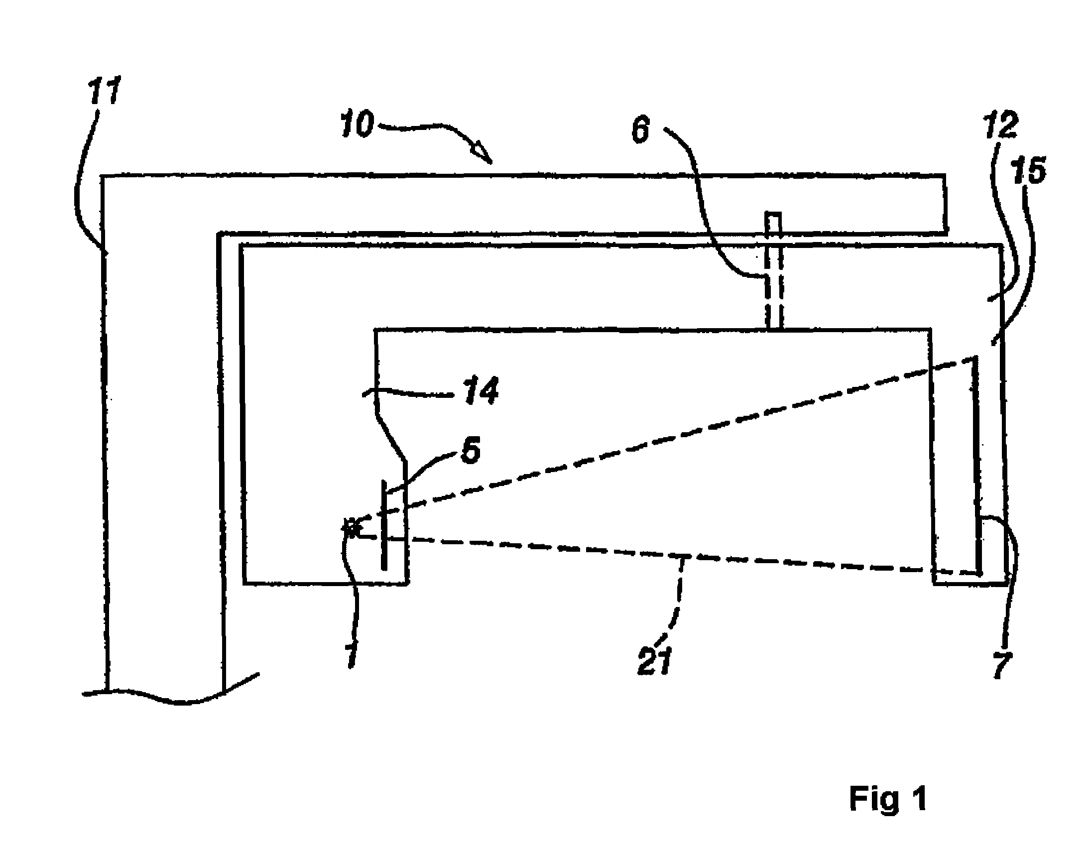
[0012]Embodiments of the invention are most conveniently used in medical X-radiography, wherein a patient is not totally exposed to radiation from every direction, since the amount of radiation received by the patient must be minimized or since there is no actual reason to irradiate the patient except from within a limited angle. The imaging performed by means of a panoramic imaging apparatus in dental X-radiography is a good example of medical X-ray imaging with no need to irradiate a patient except from within a limited angle in order to enable capturing necessary images of the patient's denture or elsewhere from the head and neck area.

[0013]Referring to FIG. 1, there is shown an exemplary view of a panoramic dental imaging apparatus, enabling the compilation of three-dimensional X-radiographic information about an imaged object. A panoramic imaging apparatus 10 shown in FIG. 1 includes a vertical member 11 from which extends a horizontal member 10, in support of which is suspende...


PUM


Abstract

The invention relates to a method for eliminating error elements caused by movements of an imaged object in X-radiography, said method comprising performing X-radiography on an imaged object for compiling three-dimensional X-radiographic information. The method comprises creating a model geometry of an X-ray imaging process, said creation work comprising a determination of the location for two or more position markers in a set of coordinates graded for an X-ray imaging apparatus. When X-radiography of an imaged object is completed, predictions are worked out regarding the locations of position markers during the imaging session. The locations and predictions determined on the basis of the model geometry are used as a basis for defining projected or most likely locations for the position markers and an automatic position markers identification method is applied for finding the locations of position markers from within a search area in the X-radiographic information. When the locations of at least two position markers have been found with the automatic position markers identification method, a minimization of offsets between the projected locations of position markers and the locations of position markers looked up by the automatic identification method is performed by searching for a minimum point of the function for eliminating the error elements resulting from movements of an imaged object.

Description

FIELD OF THE INVENTION[0001]The objective in medical X-radiography is to provide images of an object as high quality as possible from the standpoint of a diagnostic effort.BACKGROUND OF THE INVENTION[0002]In order to enable creating a three-dimensional model of an object by X-radiography, the object must be radiographed from more than one direction. However, the creation of a sufficiently precise three-dimensional model in medical X-radiography requires that imaging be effected from a plurality of directions and effective calculation algorithms be utilized. In medical X-radiography, it is a human being that constitutes the imaged object and, hence, the imaged object shall be subsequently referred to as a patient.[0003]One of the most serious sources of error in three-dimensional medical X-radiography results from movements of a patient during the imaging session. This source of error, even if an X-ray image may not be totally ruined thereby, results in X-ray images which are more bl...

Claims


Application Information

Patent Timeline
IPC IPC(8): H05G1/28H05G1/02
CPCA61B6/08A61B6/5264A61B6/466A61B6/12
Inventor SETALA, HENRI
Owner PALODEX GROUP
Why Eureka
Try Eureka