
Minimizing saturation caused by power transfer in a communication system transformer

a technology of communication system and transformer, applied in the field of communication system, can solve the problems of communication signal asymmetry and/or amplitude reduction, and achieve the effect of minimizing magnetic flux imbalance, increasing supply current, and increasing magnetic flux imbalan

Active Publication Date: 2007-12-06
AVAGO TECH INT SALES PTE LTD
View PDF3 Cites 29 Cited by
  • Summary
  • Abstract
  • Description
  • Claims
  • Application Information

AI Technical Summary

Benefits of technology

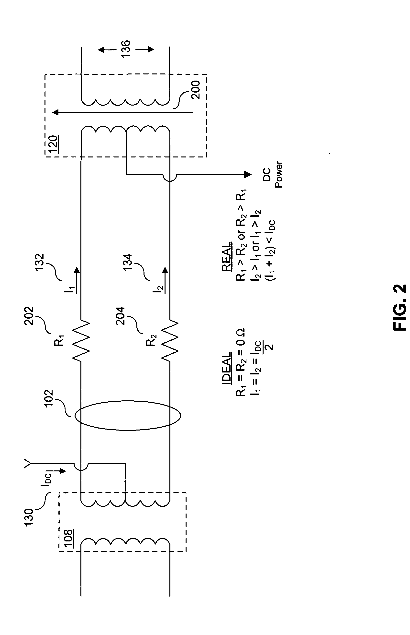
[0014]A third exemplary method for detection of the magnetic flux imbalance measures power demand by a powered device. Power demand is measured by measuring the powered device's supply current. If power demand of the powered device increases, the supply current increases. The increase in supply current increases the magnetic flux imbalance.

Problems solved by technology

The communication signal becomes asymmetric and / or suffers a reduction in amplitude when the transformer is saturated or near saturation conditions due to a magnetic flux imbalance.

Method used


Image

  • Minimizing saturation caused by power transfer in a communication system transformer
  • Minimizing saturation caused by power transfer in a communication system transformer
  • Minimizing saturation caused by power transfer in a communication system transformer

Examples


Embodiment Construction

[0029]As introduced above, an approach to minimizing saturation caused by power transfer in a communication system transformer. FIGS. 3-9, described below, illustrate this approach.

Detection and Compensation Circuits

[0030]FIG. 3 illustrates a powered device 316 according to embodiments of the invention. The powered device 316 detects and minimizes saturation of a transformer 320. The transformer 320 is part of a Power-over-Ethernet system. Alternatively, the transformer 320 is part of a communication system in which power is transferred via communication lines. The powered device 316 has a detection circuit 300, a compensation circuit 302, and a powered device transceiver 324. The winding 304 is at least one device that is located within a magnetic flux of the transformer 320. The winding 304 converts between electrical energy and magnetic energy. The winding 304 is a coil, part of the transformer 320, or a similar device.

[0031]The detection circuit 300 senses a magnetic flux imbala...


PUM


Abstract

A method and apparatus that minimizes saturation caused by power transfer in a communication system transformer, such as a transformer found in a Power-over-Ethernet system. A magnetic flux imbalance causing saturation in the transformer is detected. A compensation current is injected into a winding to minimize the magnetic flux imbalance and saturation.

Description

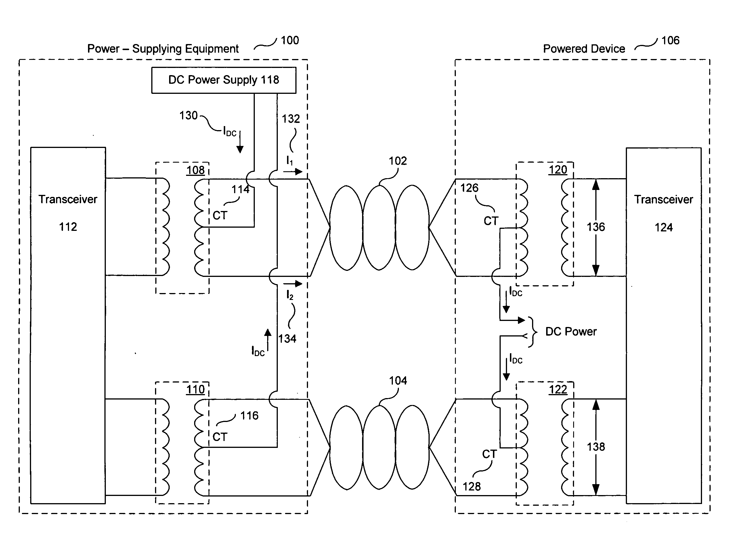
CROSS REFERENCE TO RELATED APPLICATIONS[0001]This application claims benefit of U.S. Provisional Patent No. 60 / 810,151, filed on Jun. 2, 2006, which is incorporated by reference herein in its entirety.FIELD OF THE INVENTION[0002]The present invention is generally directed to communication systems. More particularly, the invention relates to minimizing saturation caused by power transfer in a communication system transformer.BACKGROUND OF THE INVENTION[0003]Recent advances in communication network technology are driving demand for remote devices that are coupled to a communication network. This drives a need to power these remote devices. One method of providing power to a remote device is over a hardwired communication network connection. Typical remote devices are internet protocol phones and wireless access points.[0004]FIG. 1 shows a circuit for power transfer over a typical communication system connection to a powered device 106 that is remotely located relative to power-supplyi...

Claims


Application Information

Patent Timeline
IPC IPC(8): H04M1/00H04M9/00
CPCH04B3/30H04L25/0266H04L12/10H04B3/44
Inventor FALLAHI, SIAVASHBROWN, KEVIN
Owner AVAGO TECH INT SALES PTE LTD
Learn More