Tool holder with spherical contact points

Inactive Publication Date: 2007-12-06
KENNAMETAL INC
View PDF17 Cites 40 Cited by
  • Summary
  • Abstract
  • Description
  • Claims
  • Application Information

AI Technical Summary

Benefits of technology

[0004]Briefly, according to this invention, there is provided tool holder for minimizing a surface area between a cutting insert and support sidewalls of the tool holder. In one embodiment, the tool holder comprises a head portion including an insert pocket defined by a seat surface and at least on

Problems solved by technology

Unfortunately, surfaces of the cutting insert may become slightly distorted due to the sintering process.
A further grinding process may minimize or eliminate these surface distortions, but not all of the surfaces on the insert may be ground because of the extra cost associated with the grinding process.
The distortion on the surfaces of the insert that were introduced during the sintering process may cause the cutting

Method used


Image

  • Tool holder with spherical contact points
  • Tool holder with spherical contact points
  • Tool holder with spherical contact points

Examples


Embodiment Construction

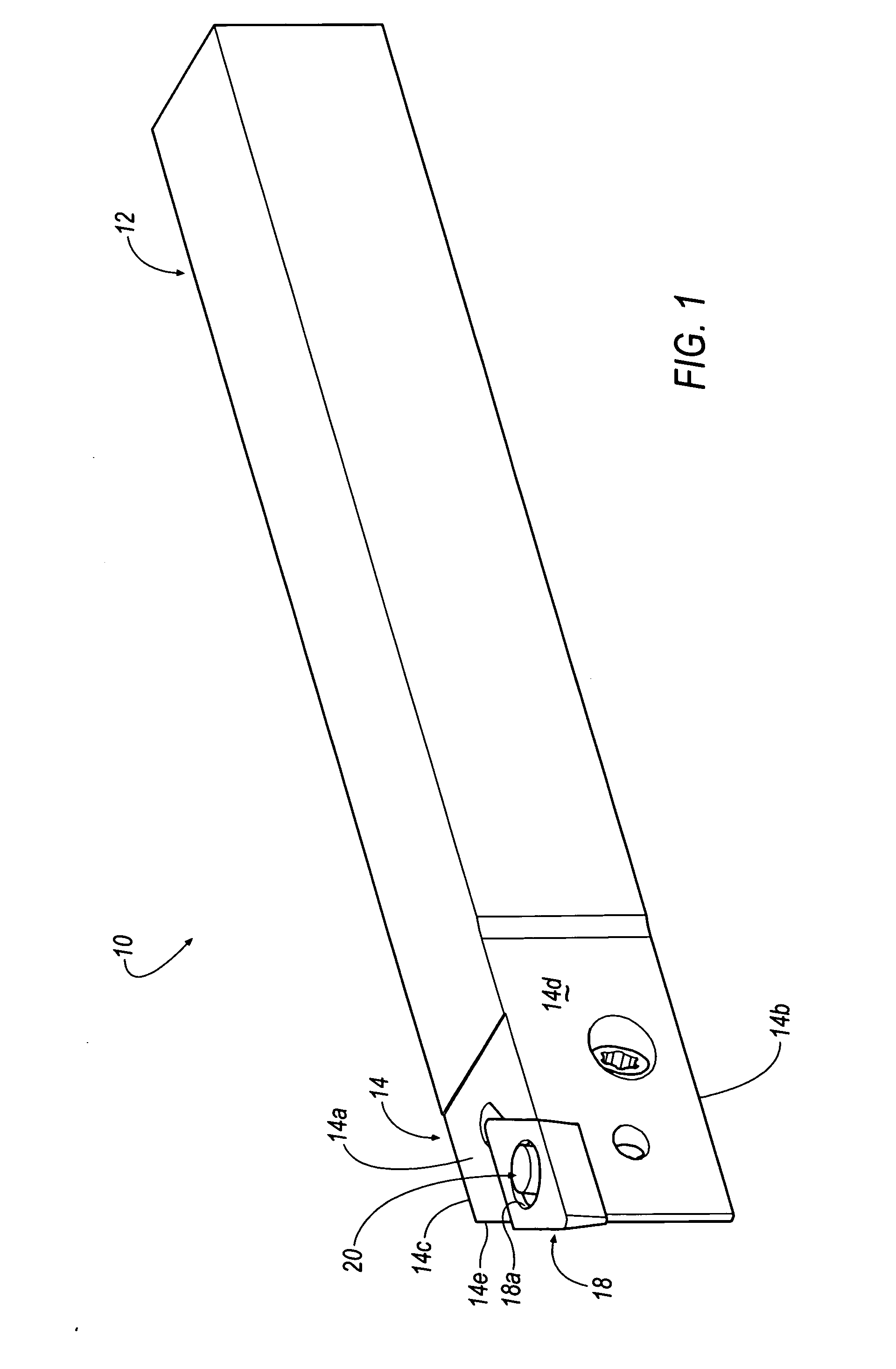
[0015]Referring to the drawings, wherein like reference characters represent like elements, FIGS. 1-3 show a tool holder, shown generally at 10, according to an embodiment of the invention. In the illustrated embodiment, the tool holder 10 comprises a lathe tool that includes a generally rectangular or square-shaped shank portion 12 and a head portion 14 defined by a top surface 14a, a bottom surface 14b, a first side surface 14c, an opposite second side surface 14d, and a third side surface 14e that may be formed at an angle with respect to with respect to the side surfaces 14c, 14d.

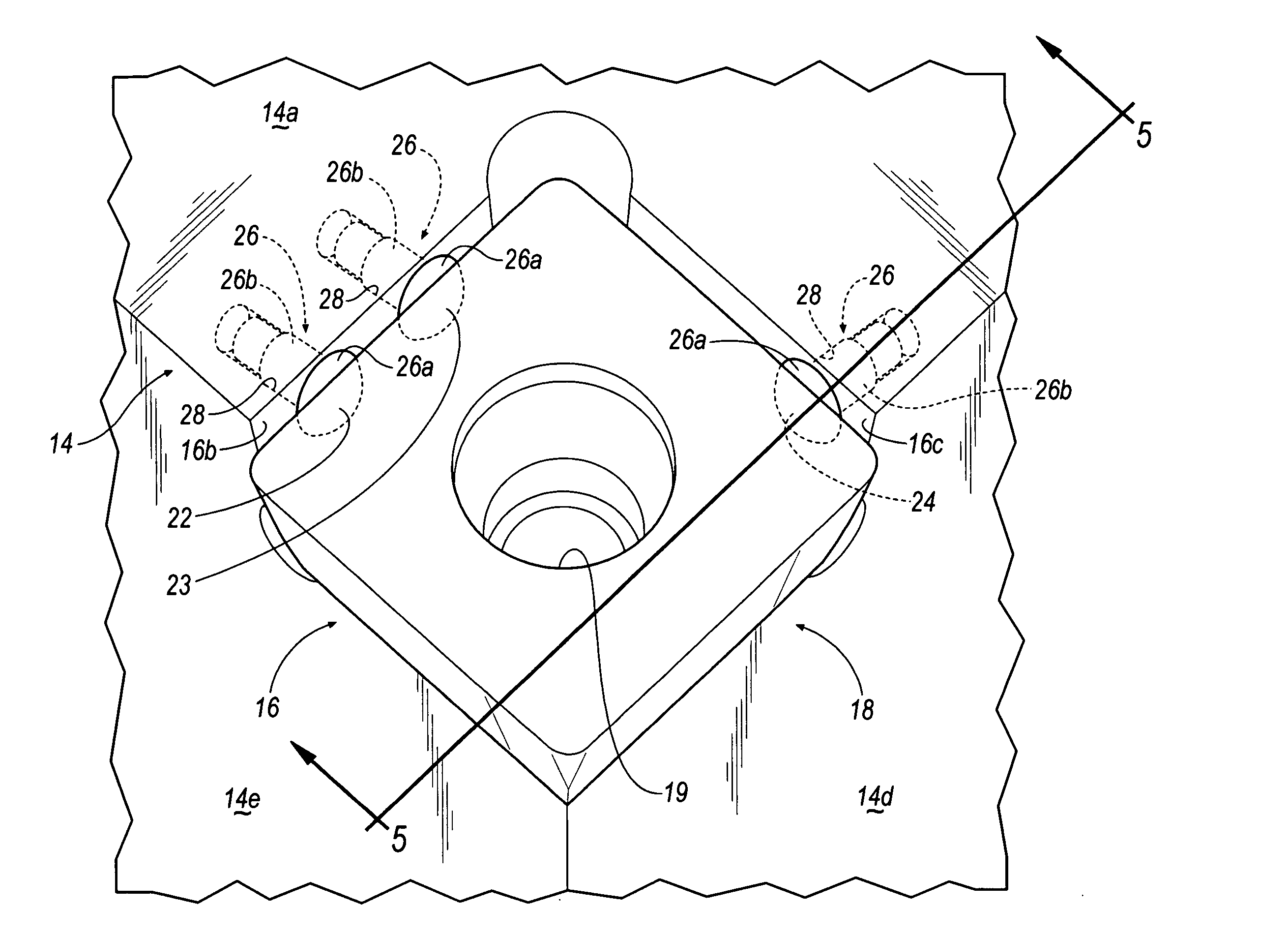
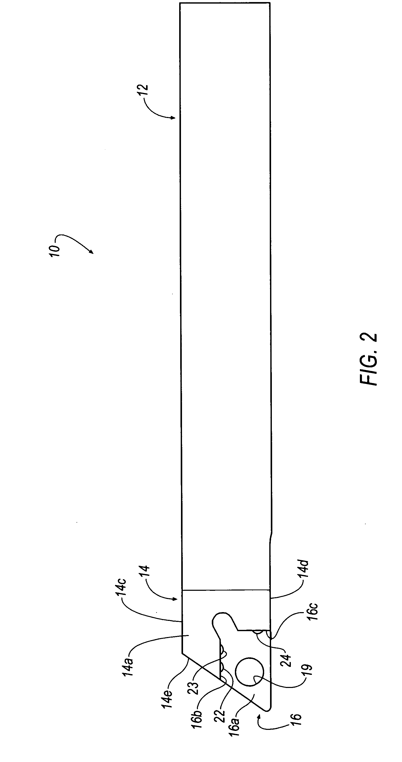
[0016]Referring now to FIGS. 2 and 3, the head portion 14 has an insert pocket 16 for retaining an insert 18 therein. The insert pocket 16 comprises a base or seat surface 16a, a first or radial support sidewall 16b and a second or axial support sidewall 16c. However, it will be appreciated by those skilled in the art that the invention can be practiced with any tool holder design that includes an inse...


PUM

PropertyMeasurementUnit
Heightaaaaaaaaaa
Heightaaaaaaaaaa
Heightaaaaaaaaaa

Abstract

A tool holder includes a shank portion, a head portion that includes an insert pocket defined by a seat surface, a first or radial support sidewall and a second or axial support sidewall, and a spherical contact point protruding from one of the first and second support sidewalls. The spherical contact point minimizes a contact area between a cutting insert mounted in the insert pocket and one of the first and second support sidewalls of the insert pocket. In one embodiment, the radial support sidewall includes two spherical contact points, and the axial support sidewall includes one spherical contact point. The spherical contact point may be formed by inserting a rivet-like structure into an aperture formed in the support sidewalls of the pocket.

Description

BACKGROUND OF THE INVENTION[0001]During manufacturing of a cutting insert, the cutting insert undergoes a sintering process. Unfortunately, surfaces of the cutting insert may become slightly distorted due to the sintering process. A further grinding process may minimize or eliminate these surface distortions, but not all of the surfaces on the insert may be ground because of the extra cost associated with the grinding process.[0002]It is important that the insert be securely seated in the pocket of the tool holder during a machining operation. The distortion on the surfaces of the insert that were introduced during the sintering process may cause the cutting insert to be improperly seated in the pocket of the tool holder. This improper seating could lead to excessive runout of the system.[0003]Several attempts have been made to minimize the contact area between the cutting insert and the pocket of the tool holder. One such attempt is to provide the pocket wall and / or the cutting ins...

Claims


Application Information

Patent Timeline
IPC IPC(8): B26B3/00
CPCB23B27/1662B23B2205/12B23C5/109B23C5/2208Y10T407/192Y10T407/23Y10T407/1936Y10T407/22Y10T407/2266Y10T407/19Y10T407/1944Y10T407/2274B23C2210/168
Inventor KOVAC, JEFFREY F.
Owner KENNAMETAL INC
Why Eureka
Try Eureka