Turbine airfoil with floating wall mechanism and multi-metering diffusion technique

a turbine airfoil and floating wall technology, applied in the field of turbine airfoils, can solve problems such as the likelihood of failure, and achieve the effects of reducing the velocity of cooling fluid, minimizing the velocity, and eliminating localized hot spots

Inactive Publication Date: 2007-12-06
SIEMENS ENERGY INC
View PDF18 Cites 32 Cited by
  • Summary
  • Abstract
  • Description
  • Claims
  • Application Information

AI Technical Summary

Benefits of technology

[0006]During operation, the cooling fluids may flow from a cooling fluid supply source (not shown) through the endwall at the OD of the turbine airfoil. The cooling fluids may flow into the central cooling fluid supply chambers, including the forward and aft central cooling fluid supply chambers. The cooling fluids may flow into the first metering holes. The velocity and rate of fluid flow into the first metering holes may be controlled by the cross-sectional area of the first metering holes. The cooling fluids may then diffuse into the outer wall diffusion chambers. The velocity of the cooling fluids may be reduced due to the larger cross-sectional area in the outer wall diffusion chambers. The cooling fluids may then be further metered by flowing through the second metering holes and into the interlayer diffusion chambers. In the interlayer diffusion chambers, the cooling fluids may impinge on a backside surface of the floating wall. This cooling fluids flow pattern allows the cooling air to uniformly disperse into the interlayer, to uniformly receive heat from the interlayer, and to control the amount of cooling fluids discharged into the film cooling slots. The spent cooling air may be discharged from the airfoil through the film cooling slots positioned between adjacent segments of the floating wall. This cooling mechanism may be repeated throughout the outer walls in the pressure and suction sides. Other cooling fluids may be expelled out of the central cooling fluid supply chambers and into the leading edge impingement chamber and the trailing edge impingement chamber.
[0012]Another advantage of this invention is that the outer wall may move generally unrestrained relative to the airfoil outer wall thus enhancing the durability of the thermal barrier coating.

Problems solved by technology

In addition, turbine vanes and blades often contain cooling systems for prolonging the life of the vanes and blades and reducing the likelihood of failure as a result of excessive temperatures.

Method used


Image

  • Turbine airfoil with floating wall mechanism and multi-metering diffusion technique
  • Turbine airfoil with floating wall mechanism and multi-metering diffusion technique
  • Turbine airfoil with floating wall mechanism and multi-metering diffusion technique

Examples


Embodiment Construction

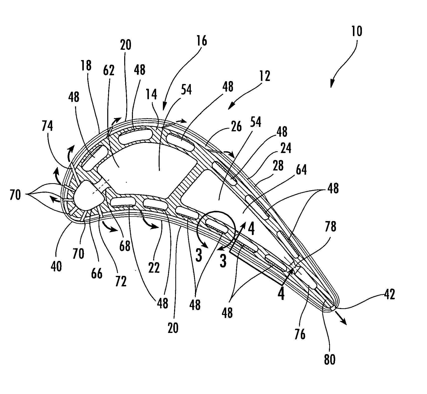
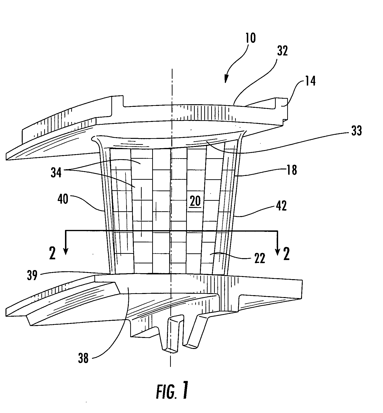
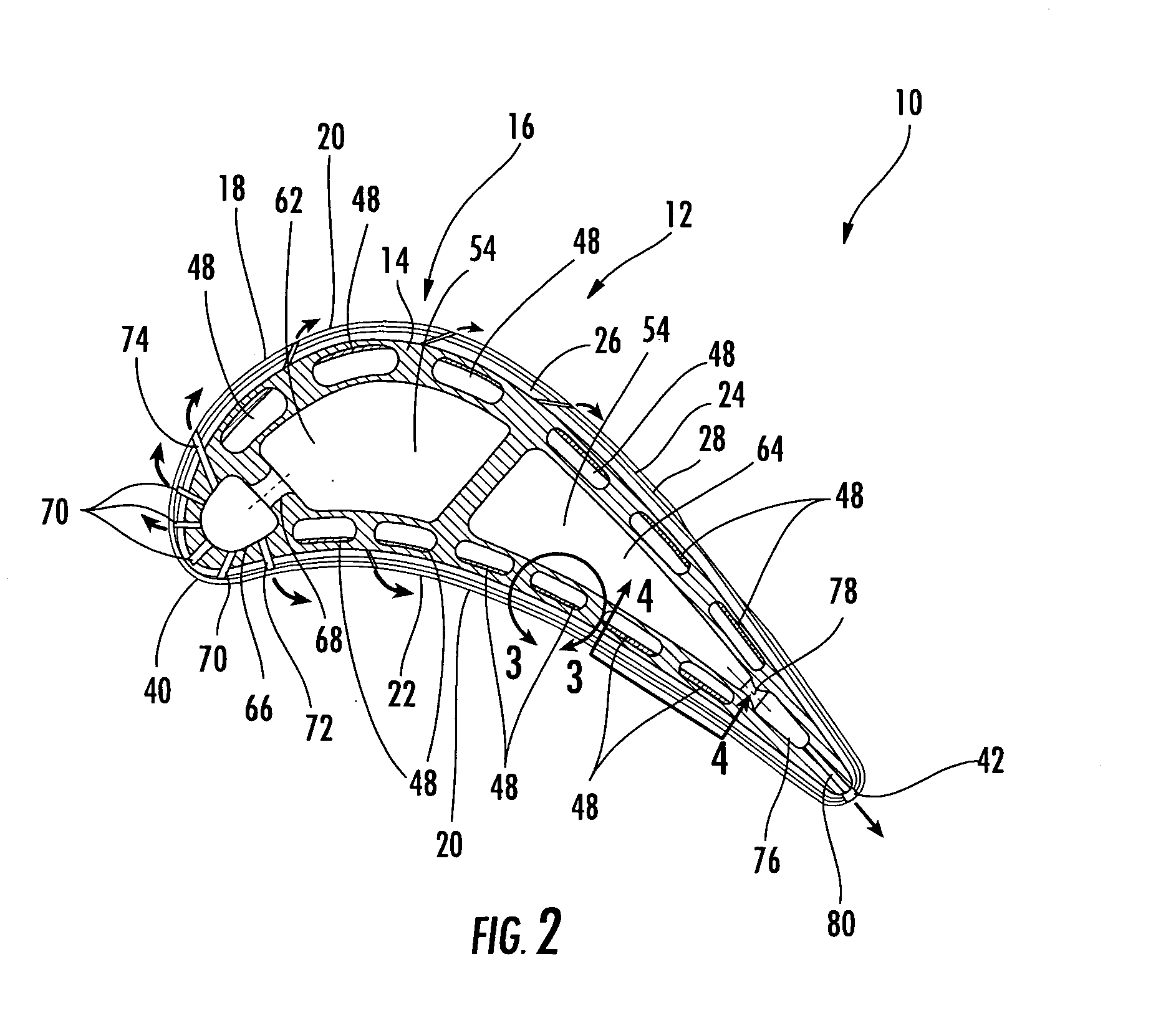
[0019]As shown in FIGS. 1-4, this invention is directed to a turbine airfoil 10 having a cooling system 12 in inner aspects of the turbine airfoil 10 for use in turbine engines. The cooling system 12 may be used in any turbine vane or turbine blade. While the description below focuses on a cooling system 12 in a turbine vane 10, the cooling system 12 may also be adapted to be used in a turbine blade. The cooling system 12 may be configured such that adequate cooling occurs within an outer wall 14 of the turbine vane 10 by including one or more cavities 16 in the outer wall 14 and configuring each cavity 16 based on local external heat loads and airfoil gas side pressure distribution in both chordwise and spanwise directions. The chordwise direction is defined as extending between a leading edge 40 and a trailing edge 42 of the airfoil 10. The spanwise direction is defined as extending between an endwall 32 at a first end 33 and an inner endwall 38 at a second end 39.

[0020]As shown i...


PUM

PropertyMeasurementUnit
temperaturesaaaaaaaaaa
ODaaaaaaaaaa
pressureaaaaaaaaaa

Abstract

A turbine airfoil usable in a turbine engine and having at least one cooling system. The turbine airfoil may include an interlayer coupled to an outer surface of the outer wall of the airfoil, wherein the interlayer may be formed from a porous material that allows cooling fluids to pass through the interlayer. The floating wall may be coupled to an outer surface of the interlayer, wherein the floating wall may be formed from a plurality of floating wall segments positioned in close proximity to each other but with a film cooling slot positioned between the adjacent wall segments to enable cooling fluids to be exhausted from the elongated hollow airfoil. The cooling system may include an outer wall diffusion chamber positioned in the outer wall and an interlayer diffusion chamber. One or more metering holes may be in communication with the outer wall and interlayer diffusion chambers.

Description

FIELD OF THE INVENTION[0001]This invention is directed generally to turbine airfoils, and more particularly to hollow turbine airfoils having cooling channels for passing fluids, such as air, to cool the airfoils.BACKGROUND[0002]Typically, gas turbine engines include a compressor for compressing air, a combustor for mixing the compressed air with fuel and igniting the mixture, and a turbine blade assembly for producing power. Combustors often operate at high temperatures that may exceed 2,500 degrees Fahrenheit. Typical turbine combustor configurations expose turbine vane and blade assemblies to these high temperatures. As a result, turbine vanes and blades must be made of materials capable of withstanding such high temperatures. In addition, turbine vanes and blades often contain cooling systems for prolonging the life of the vanes and blades and reducing the likelihood of failure as a result of excessive temperatures.[0003]Typically, turbine vanes are formed from an elongated port...

Claims


Application Information

Patent Timeline
Patent Type & Authority Applications(United States)
IPC IPC(8): F01D5/18
CPCF01D5/186F05D2300/612F05D2260/202F01D5/187
Inventor LIANG, GEORGE
Owner SIEMENS ENERGY INC
Why Eureka
Try Eureka