
Color forming compositions with improved marking sensitivity and image contrast and associated methods

a color forming composition and marking sensitivity technology, applied in thermography, instruments, photosensitive materials, etc., can solve the problems of slow development time, less than acceptable contrast, adversely affecting the performance of the disk upon spinning at high speed, etc., to improve the marking sensitivity and improve the image contrast. , the effect of rapid developmen

Inactive Publication Date: 2007-12-06
HEWLETT PACKARD DEV CO LP
View PDF49 Cites 15 Cited by
  • Summary
  • Abstract
  • Description
  • Claims
  • Application Information

AI Technical Summary

Benefits of technology

[0006] It has been recognized that it would be advantageous to provide rapidly developable color forming compositions with improved marking sensitivity, which can also be used to provide images with improved image contrast, even under fast development conditions. In one aspect of the present invention, a color forming composition can include a polymeric activator phase including a polymer matrix and an activator dissolved therein, a color former phase including a color former, and a radiation absorber in thermal contact with the color former phase. Particularly, the color former phase can be finely dispersed within the polymeric activator phase at an average particle size of less than 2 μm.

Problems solved by technology

While this method can provide a wide variety of label content, it tends to be cost ineffective for production of less than about 400 customized disks because of the fixed costs associated with preparing a stencil or combination of stencils and printing the desired pattern or graphic display.
Most consumer available methods of labeling are limited to either handwritten descriptions which lack professional appearance, quality and variety, or preprinted labels which may be affixed to the disk, but which can also adversely affect the disk performance upon spinning at high speeds.
However, many of these color forming compositions have development sensitivities that result in slower development time and / or less than acceptable contrast.

Method used


Image

  • Color forming compositions with improved marking sensitivity and image contrast and associated methods
  • Color forming compositions with improved marking sensitivity and image contrast and associated methods

Examples


example 1

[0076] a) Preparation of Color Former Particles for Color Former Phase (Discontinuous Phase)

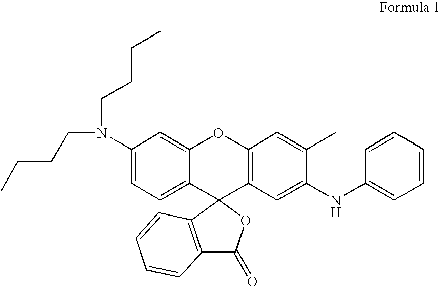
[0077] About 10 g of m-terphenyl (accelerator) was melted in a beaker, and the melt was heated to about 110° C. About 100 g of BK400 was added in small increments to the melt upon constant stirring. The added BK400 is a leuco-dye (2′-anilino-3′-methyl-6′-(dibutylamino)fluoran) available from Nagase Corporation, the structure of which is set forth below as Formula 1:

The temperature of the mixture was increased up to about 170° C. to 180° C. Stirring was continued until complete dissolution of BK400 in the melt (usually takes about 10 to 15 min) was obtained to form an accelerator / leuco dye solution. Next, about 1.8 g of Cirrus-715 (radiation absorber IR dye) was added to the melt upon constant stirring. Heating and stirring was continued for about two to three additional minutes until the Cirrus-715 was completely dissolved in the melt to form a leuco dye / antenna / accelerator alloy (eutecti...

example 2

[0082] a) Preparation of Color Former Particles for Color Former Phase (Discontinuous Phase)

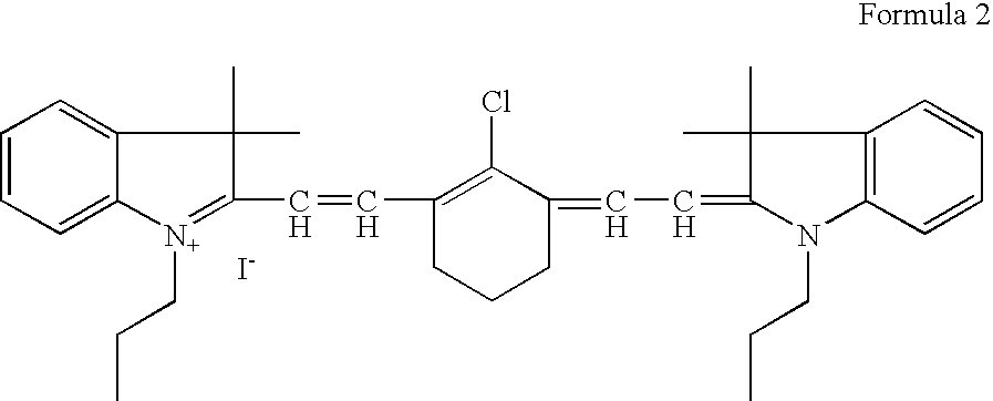
[0083] About 10 g of m-terphenyl (accelerator) was melted in a beaker, and the melt was heated to about 110° C. About 100 g of BK400 was added in small increments to the melt upon constant stirring. The added BK400 is a leuco-dye (2′-anilino-3′-methyl-6′-(dibutylamino)fluoran) available from Nagase Corporation, the structure of which is set forth in Formula 1 above. The temperature of the mixture was then increased up to about 170° C. to 180° C. Stirring was continued until complete dissolution of BK400 in the melt (usually takes about 10 to 15 min) was obtained to form an accelerator / leuco dye solution melt. About 1.2 g of IR780-iodide (radiation absorber IR dye) was then added to the melt upon constant stirring. IR780-iodide is also known as 3H-Indolinium, 2-[2-chloro-3-[91,3-dihydro3,3-dimethyl-1-propyl-2H-indol-2-ylidene)ethylidene]-1-cyclohexen-1yl]ethenenyl]-3,3-dimethyl-1-propyl-, iod...

example 3

[0088] a) Preparation of Color Former Particles for Color Former Phase (Discontinuous Phase)

[0089] About 10 g of m-terphenyl (accelerator) was melted in a beaker, and the melt was heated to about 110° C. About 100 g of BK400 was added in small increments to the melt upon constant stirring. The added BK400 is a leuco-dye (2′-anilino-3′-methyl-6′-(dibutylamino)fluoran) available from Nagase Corporation, the structure of which is set forth in Formula 1 above. The temperature of the mixture was increased up to about 170° C. to 180° C. Stirring was continued until complete dissolution of BK400 in the melt (usually takes about 10 to 15 min) was obtained to form an accelerator / leuco dye solution. Next, about 1.8 g of Cirrus-715 (radiation absorber IR dye) was added to the melt upon constant stirring. Heating and stirring was continued for about two to three additional minutes until the Cirrus-715 was completely dissolved in the melt to form a leuco dye / antenna / accelerator alloy (eutectic)...


PUM

PropertyMeasurementUnit
particle sizeaaaaaaaaaa
developing wavelengthaaaaaaaaaa
particle sizeaaaaaaaaaa

Abstract

Compositions and methods for production of color images which are developable with improved marking sensitivity and image contrast are disclosed and described. Specifically, a color forming composition can comprise a polymeric activator phase including a polymer matrix and an activator dissolved therein, a color former phase including a color former, and a radiation absorber in thermal contact with the color former phase. Particularly, the color former phase can be finely dispersed within the polymeric activator phase at an average particle size of less than 2 μm.

Description

FIELD OF THE INVENTION [0001] The present invention relates generally to color forming compositions. More particularly, the present invention relates to methods and compositions which can form images upon interaction with energy, such as light energy, with improved marking sensitivity and image contrast. BACKGROUND OF THE INVENTION [0002] Compositions which produce a color change upon exposure to energy in the form of light or heat are of great interest in producing images on a variety of substrates. Optical disks represent a significant percentage of the market for data storage of software as well as of photographic, video, and / or audio data. Typically, optical disks have data patterns embedded thereon that can be read from and / or written to one side of the disk, and a graphic display or label printed on the other side of the disk. [0003] In order to identify the contents of the optical disk, printed patterns or graphic display information can be provided on the non-data, or label,...

Claims


Application Information

Patent Timeline
Patent Type & Authority Applications(United States)
IPC IPC(8): G03C1/76G11B7/24G11B7/24035G11B7/24094G11B7/24097G11B7/254G11B7/257
CPCB41M5/30B41M5/34G11B23/40G11B7/252G03F7/105G03C1/76
Inventor KASPERCHIK, VLADEK P.GORE, MAKARAND P.
Owner HEWLETT PACKARD DEV CO LP
Learn More