Method and apparatus for selecting antenna for ranging detection in orthogonal frequency division multiple access system

a technology of orthogonal frequency division and multiple access system, applied in electrical apparatus, substation equipment, radio transmission, etc., can solve the problems of deteriorating system performance, inefficient use of system resources, and inability to provide information with respect to channel quality,

Inactive Publication Date: 2007-12-06
POS DATA CO LTD
View PDF9 Cites 17 Cited by
  • Summary
  • Abstract
  • Description
  • Claims
  • Application Information

AI Technical Summary

Benefits of technology

[0034]And the ranging channel is composed of one or more groups of six adjacent subchannels, where the groups are defined starting from the first subchannel. Optionally, ranging channel can be composed of eight adjacent subchannels using the symbol structure. The indices of the subchannels that compose the ranging channel are specified in the UL-MAP message. Users are allowed to collide on this ranging channel. To effect a ranging transmission, each user randomly chooses one ranging code from a bank of specified binary codes. These codes are then BPSK modulated onto the subcarriers in the ranging channel, one bit per subcarrier.

Problems solved by technology

However, the conventional antenna selection method using the pilot symbol has several problems when applied to the OFDM / OFDMA mobile communication system.
When an amount of frequency domain calculations, that requires a large amount of computational resources and memory resources, is increased in proportion to the total number of antennas, system resources may be very inefficiently used.
As another problem, the conventional method of selecting an antenna by comparing strength of received signals cannot provide information with respect to a channel quality in a multi-path fading channel environment.
Accordingly, when only signal strengths are compared without a signal quality index, a channel via which the desired signal is transmitted cannot be distinguished from a channel in which interference occurs, causing a selection of a suboptimal antenna and thereby deteriorating performance of the system.
Particularly, the described problem may occur excessively in a ranging interval where signals are received from a plurality of terminals at the same time.

Method used


Image

  • Method and apparatus for selecting antenna for ranging detection in orthogonal frequency division multiple access system
  • Method and apparatus for selecting antenna for ranging detection in orthogonal frequency division multiple access system
  • Method and apparatus for selecting antenna for ranging detection in orthogonal frequency division multiple access system

Examples


Embodiment Construction

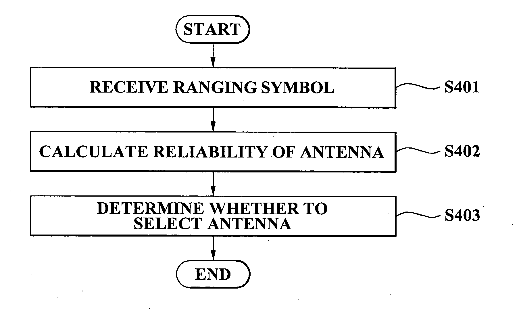
[0049]Reference will now be made in detail to the embodiments of the present invention, examples of which are illustrated in the accompanying drawings, wherein like reference numerals refer to the like elements throughout. The embodiments are described below to explain the present invention by referring to the figures.

[0050]FIG. 4 is a flowchart illustrating an antenna selection method according to an embodiment of the present invention. Hereinafter, each operation will be described with reference to FIG. 4. For reference, in FIG. 4, whether to select an individual antenna is described. However, “antenna selection” mentioned in following description includes not only determining whether to use an individual antenna but also selecting one or more antennas from a plurality of antennas.

[0051]In operation S401, at least one ranging symbol is received from each of a plurality of antennas. The ranging symbol received in operation S401 is expressed as a time domain signal. As described abo...


PUM


Abstract

A method of selecting an antenna for ranging detection in an orthogonal frequency division multiple access system, the method including: receiving at least one ranging symbol from the antenna; and determining whether to select the antenna, by correlation computing the received ranging symbol in a time domain.

Description

BACKGROUND OF THE INVENTION[0001]1. Field of the Invention[0002]The present invention relates to an antenna selection method and apparatus for effectively performing ranging detection in an orthogonal frequency division multiple access (OFDMA) mobile communication system.[0003]2. Description of the Related Art[0004]A mobile communication system based on a theory of electromagnetic wave propagation via a wireless channel transmits and receives a signal by using antennas installed at a transmitting end and a receiving end, respectively. Particularly, in the case of the receiving end, since all processes of receiving a wireless signal, obtaining a symbol, and extracting data start at the antenna, entire system performance largely depends on antenna performance.[0005]Accordingly, the receiving end may include a plurality of antennas and may have a function of selecting a certain antenna for transmitting and receiving a signal with the transmitting end. Particularly, when communicating w...

Claims


Application Information

Patent Timeline
Patent Type & Authority Applications(United States)
IPC IPC(8): H04B1/00H04B1/06H04M1/00
CPCH04B7/0857
Inventor CHOI, JOONSANG
Owner POS DATA CO LTD
Why Eureka
Try Eureka