Tracking control method and electron beam writing system

Active Publication Date: 2009-05-28
NUFLARE TECH INC
View PDF16 Cites 19 Cited by
  • Summary
  • Abstract
  • Description
  • Claims
  • Application Information

AI Technical Summary

Benefits of technology

[0018]It is, therefore, an object of the present invention to provide a tracking control method in which an optimal subfield division number is reliably calculat

Problems solved by technology

In this writing method, however, the relationship between the speed of the movement of the stage and the deflection range of the electron beam may be not appropriate.
That is, an area irradiated with the electron beam deflected by a control system for the main deflector may deviate from the predetermined region, and the writing operation may be aborted for an abnormality.
In the conventional tracking control method, however, there is a high possibility that the writing operation is stopped.
When the speed of the movement of the stage is low, however, the throughput of the electr

Method used


Image

  • Tracking control method and electron beam writing system
  • Tracking control method and electron beam writing system
  • Tracking control method and electron beam writing system

Examples


Embodiment Construction

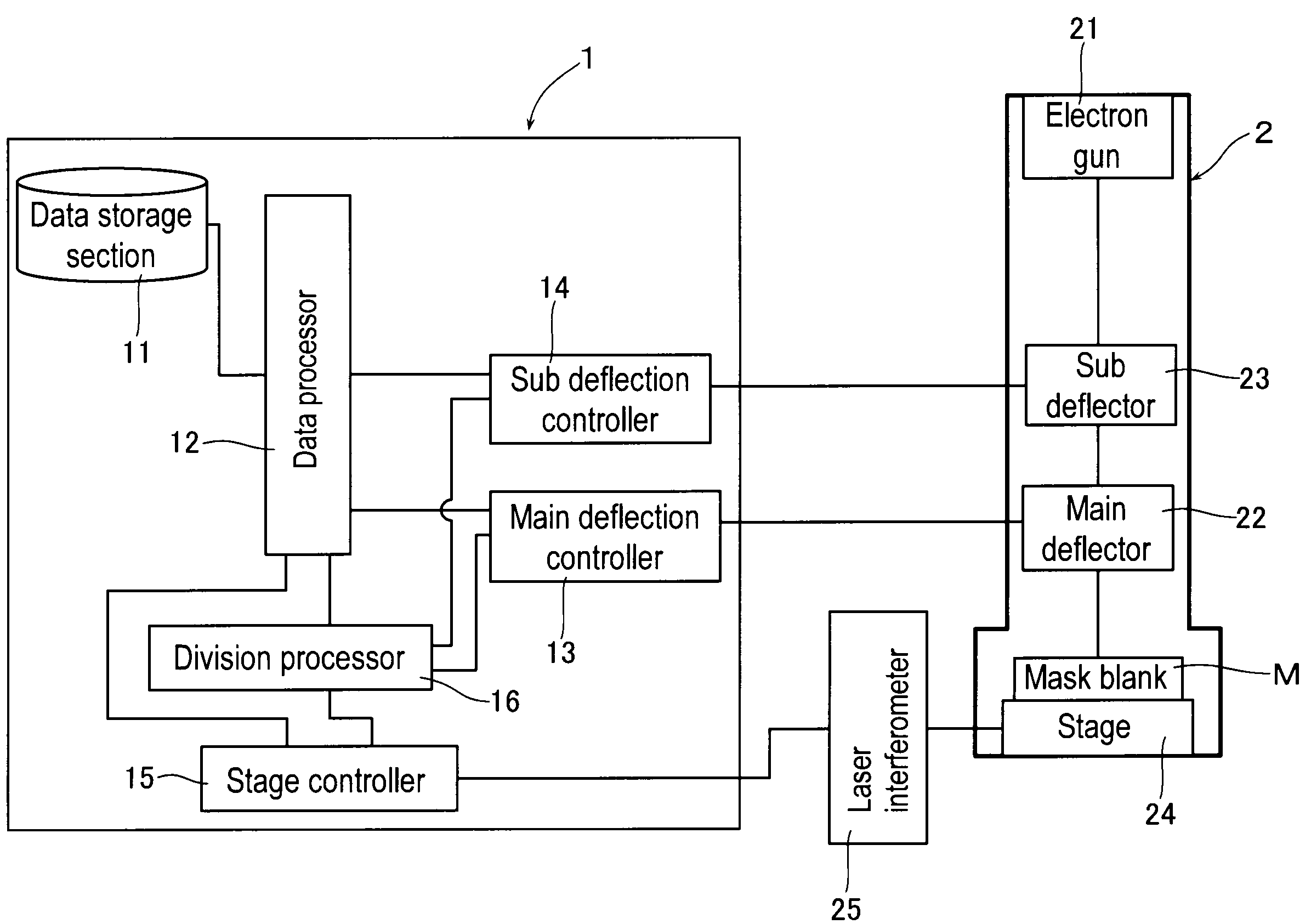
[0025]The tracking control in an electron beam writing apparatus is performed by constantly measuring the position of a moving stage in X-Y coordinates by means of a laser interferometer or the like, measuring the distance the stage has moved for the time period from the start of writing of a subfield to the completion of writing within the subfield, and correcting the position of the subfield so as to cancel a shift in shot coordinates caused by the movement of the stage. This correction is performed by controlling a voltage to be applied to a main deflector.

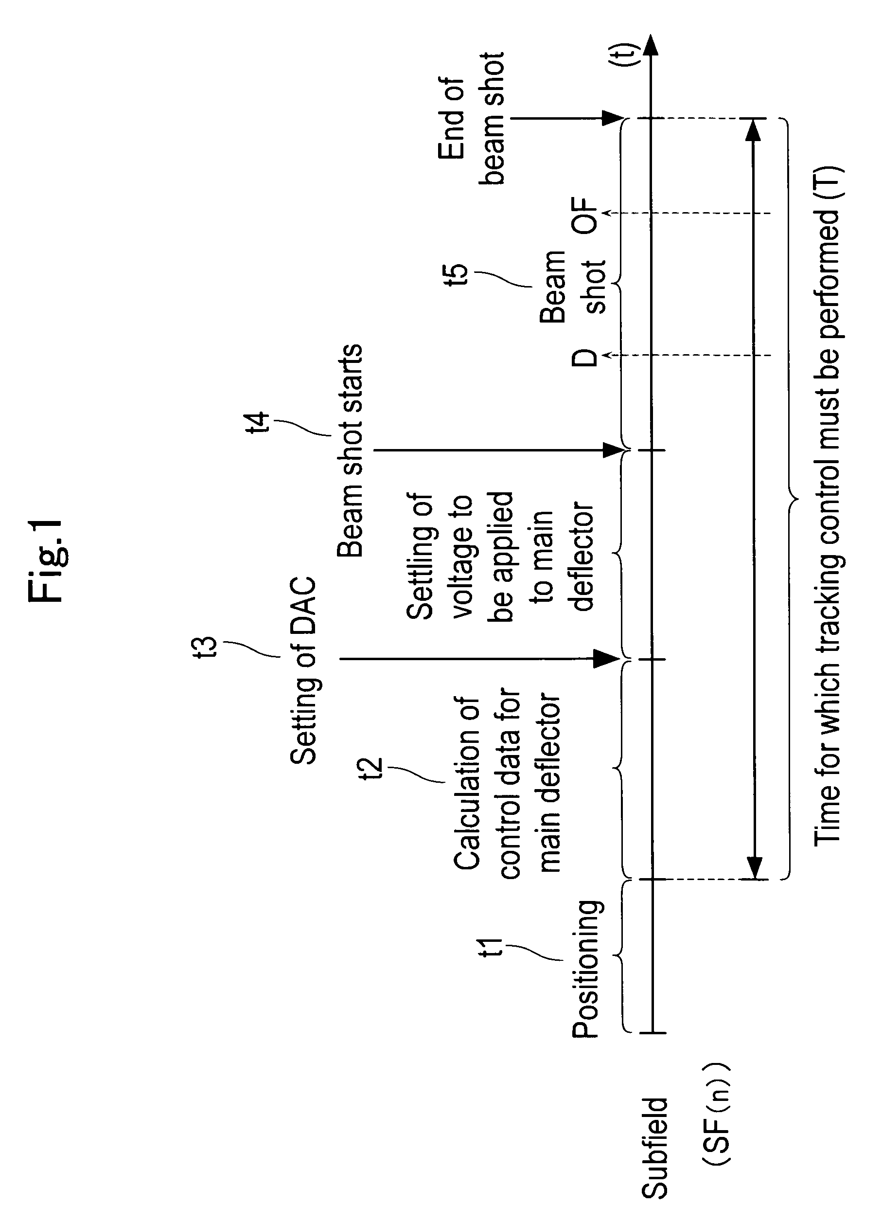
[0026]FIG. 1 is a time chart of the tracking control for a given subfield.

[0027]First, the stage mounting a mask blank thereon moves. After the subfield to be subjected to the tracking control reaches a region in which a pattern can be written, the operation of positioning the subfield is performed for a time t1.

[0028]After the positioning, the operation of calculating control data for the main deflector is performed for a time...


PUM


Abstract

Control data for a main deflector is calculated based on position data that specifies the position of a region to be irradiated with the electron beam on the subfield, data on the number of all beam shots on the subfield, data on a time required for all the beam shots, and stage data that specifies the position of the stage. When the number of beam shots on one of the divided subfield sections reaches the obtained number of the beam shots on each of the divided subfield sections, a writing process proceed to a writing operation to be performed on another one of the divided subfield sections based on the direction of the movement of the stage.

Description

BACKGROUND OF THE INVENTION[0001]1. Field of the Invention[0002]The present invention relates to a tracking control method in which a main deflector deflects an electron beam to ensure that a region in a subfield of a mask blank placed on the stage that continuously moves is irradiated with the electron beam in accordance with the movement of the stage and to an electron beam writing system having means for performing the tracking control method, and more particularly to a tracking control method and an electron beam writing system capable of avoiding an abnormality of tracking.[0003]2. Background Art[0004]In recent years, an electron beam writing apparatus has used a vector scanning method to improve the throughput of the apparatus. In the vector scanning method, an electron beam is deflected only to a region (on a mask blank) in which a pattern is to be written. Specifically, in the vector scanning method, a stage having the mask blank thereon is continuously moved, and tracking c...

Claims


Application Information

Patent Timeline
IPC IPC(8): G21K5/10G03F1/76G03F1/78H01J37/305H01L21/027
CPCB82Y10/00B82Y40/00H01J2237/30483H01J37/3174H01J2237/20292H01J37/3045
Inventor INOUE, HIDEO
Owner NUFLARE TECH INC
Why Eureka
Try Eureka