
Controller for magnetic wheels

Inactive Publication Date: 2007-12-06
HER YUAN CHYUN
View PDF35 Cites 2 Cited by
  • Summary
  • Abstract
  • Description
  • Claims
  • Application Information

AI Technical Summary

Benefits of technology

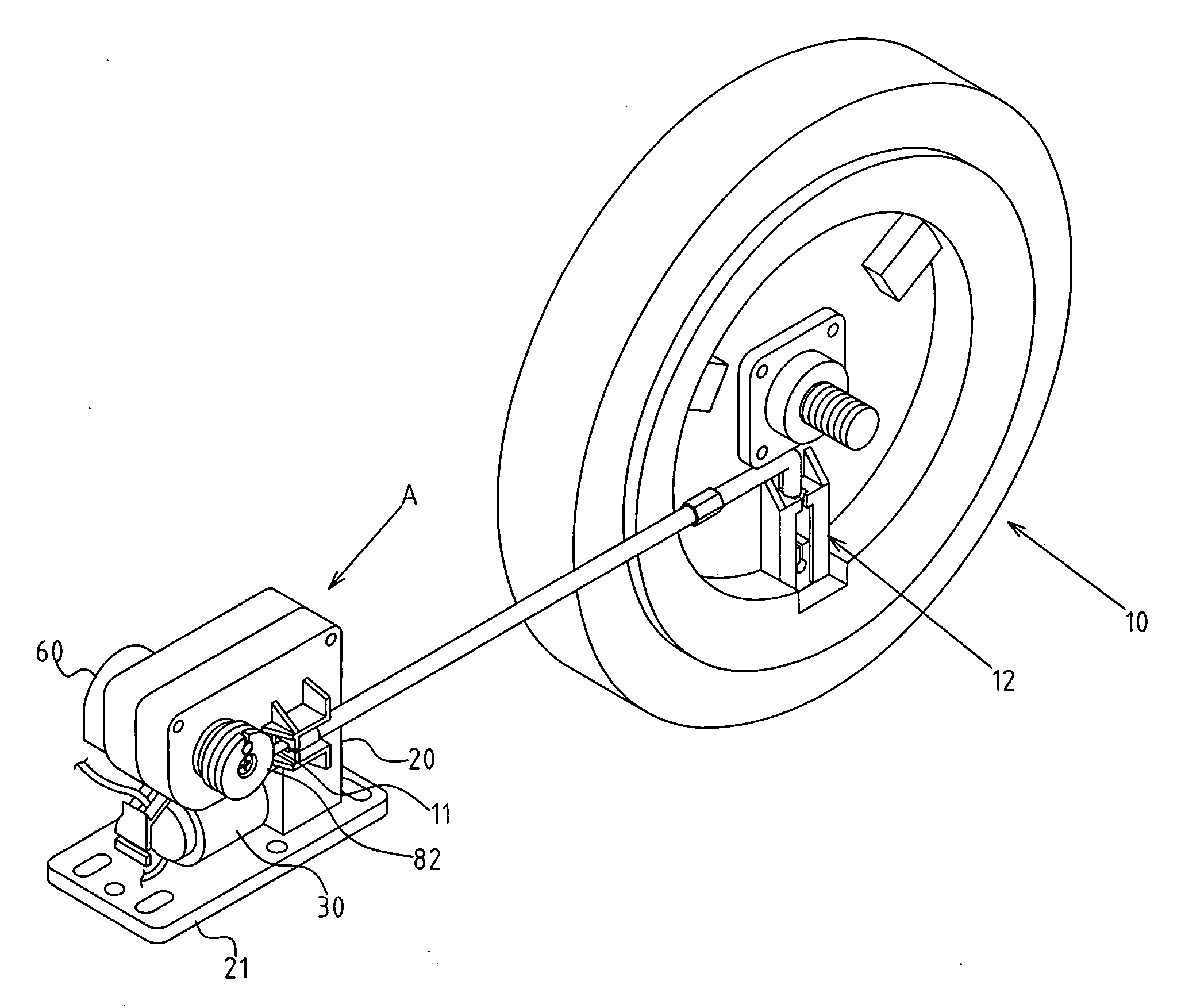
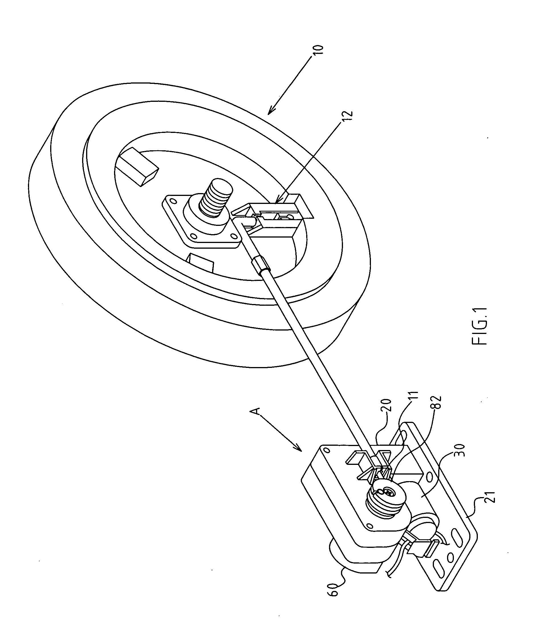
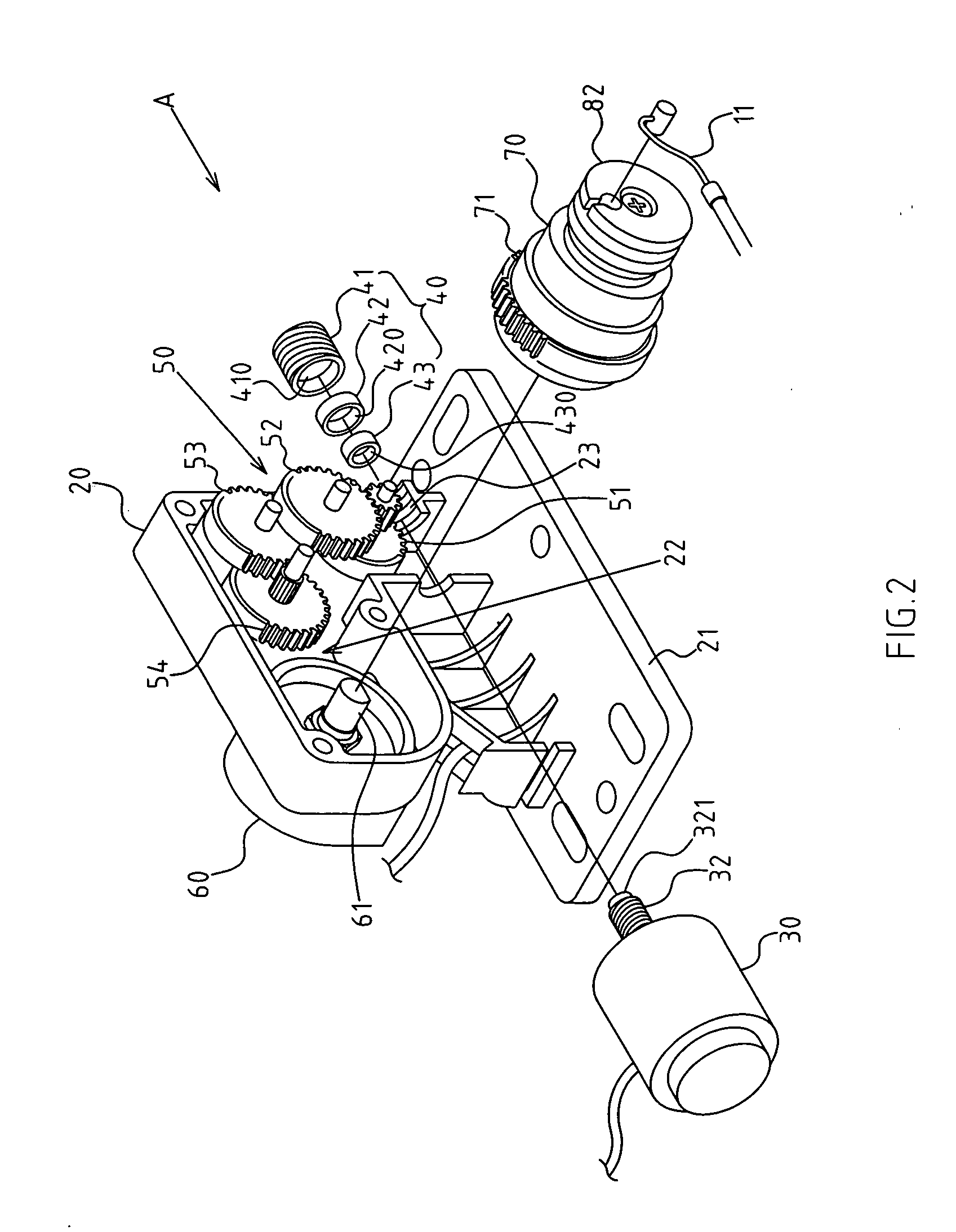
[0011]In the present invention, based upon an innovative design, an alternated adjusting seat 90 is added into hollow groove 72 of external rotary disk 70 of a magnetic wheel 10 controller (A). A flexible locker 92 of the alternated adjusting seat 90 can be flexibly locked into a second latch groove 74 of a hollow groove 72. During the initial assembly of the magnetic wheel 10 and controller (A), when cam shaft 61 of tester 60 has rotated to the stop position but a magnetic component 12 of magnetic wheel 10 has not reached the desired location, the drive motor 30 will continue to rotate along with external rotary disk 70. Since flexible locker 92 is flexibly locked into second latch groove 74, external rotary disk 70 and alternated adjusting seat 90 can run alternatively without being influenced by stopped cam shaft 61 of tester 60. So, cable-driven wheel 82 continuously rotates to pull cable 11 and moves magnetic component 12 of magnetic wheel 10 into place for normal operation. No manual adjustment of cable is required, shortening assembly time and improving manufacturing efficiency.
[0012]Based upon another innovative design of the present invention, a screw support component 40 is mounted onto housing foundation 20 of controller (A). The end 321 of screw 32 of drive motor 30 can be stably supported for more reliable operation and longer service life of screw 32 and drive motor 30. With adjustable design of screw seat 41, the screw support component 40 can be securely tightened by screw 32, while output shaft 31 of drive motor 30 can be tightly locked to remove the clearance of axial deflection for a more stable rotation. Since the soft liner ring 42 is loosely coupled with tanker 410 of screw seat 41, and the adhesive is not dried, a slight shift clearance will allow soft liner ring 42 and solid coupling ring 43 to rotate synchronously with output shaft 31 and screw 32 of drive motor 30 for an optimal location. In such case, the adhesive for soft liner ring 42 is dried and soft liner ring 42 positioned. So, it can provide a stable support for screw 32, while making output shaft 31 of drive motor 30 match the central point correctly during rotation.

Problems solved by technology

In the prior art, if the pulling state of the cable mismatches the rotating state of a tester cam shaft during initial assembly of the typical magnetic wheel and controller, manual adjustment of the cable is required to avoid delay of assembly works and creates an inefficient manufacturing process.
Also, since a screw of the drive motor of the magnetic wheel controller is typically suspended without any support structure, axial thrust of a worm gear likely results in unstable deflection, unsmooth operation and mechanical damage or even shorter service life.

Method used


Image

  • Controller for magnetic wheels
  • Controller for magnetic wheels
  • Controller for magnetic wheels

Examples


Embodiment Construction

[0023]The features and the advantages of the present invention will be more readily understood upon a thoughtful deliberation of the following detailed description of a preferred embodiment of the present invention with reference to the accompanying drawings.

[0024]FIGS. 1, 2 depict preferred embodiments of magnetic wheel controllers of the present invention, which, however, are provided for only explanatory purposes regarding the claims. The magnetic wheel 10 is generally applied to fitness equipment (e.g. treadmills) as part of dampening structures. The controller (A) is used to regulate the resistance of a magnetic wheel 10.

[0025]The present invention includes a housing foundation 20, which has a mounting plate 21 (e.g. a bolt-punched hole), whereby it is permanently placed into a preset location of the fitness equipment. A space 22 is reserved within housing foundation 20 to accommodate structural members.

[0026]The structural members include a drive motor 30, which is mounted int...


PUM


Abstract

The present invention provides a controller for a magnetic wheel, which is added with an alternated adjusting seat within the external rotary disk of the magnetic wheel controller. A flexible locker of alternated adjusting seat can be flexibly locked into second latch groove of external rotary disk. When a cam shaft of a tester has not reached a signal locating point, but the cable of magnetic component has been fixed during initial assembly of the magnetic wheel and controller, the flexible lock is flexibly locked with a second latch groove, such that the external rotary disk and alternated adjusting seat will continue to rotate until the tester senses the locating signal. Thus, no manual adjustment of cable is required in order to shorten assembly time and improve manufacturing efficiency for a higher practicability.

Description

CONTROLLER FOR MAGNETIC WHEELS RELATED U.S. APPLICATIONS[0001]Not applicable.STATEMENT REGARDING FEDERALLY SPONSORED RESEARCH OR DEVELOPMENT[0002]Not applicable.REFERENCE TO MICROFICHE APPENDIX[0003]Not applicable.FIELD OF THE INVENTION[0004]The present invention relates generally to a controller for a magnetic wheel, and more particularly, to an innovative structure with an alternated adjusting seat and screw support component.BACKGROUND OF THE INVENTION[0005]Magnetic wheels are often applied to fitness equipment (e.g. treadmills) as part of dampening structures. To offer optional resistance for the benefit of different operators of the fitness equipment, a controller is required to adjust the resistance of magnetic wheels in the equipment. The present invention has provided an improved controller, which generally comprises a drive motor, variable gear set, tester and cable-driven wheel. A variable gear set and a cable-driven wheel are activated by the drive motor. In the case of r...

Claims


Application Information

Patent Timeline
IPC IPC(8): A63B22/06A63B69/16
CPCA63B21/005Y10T74/18832A63B22/02A63B21/15
Inventor LIN, HSIEN-MO
Owner HER YUAN CHYUN
Learn More