Testing of Embedded Systems

a technology of embedded systems and embedded devices, applied in the direction of testing circuits, resistance/reactance/impedence, instruments, etc., can solve the problems of complex embedded system complexity, provide developers with highly complex software solutions for embedded system design, and disrupt the desktop computer mark

Inactive Publication Date: 2007-12-06
GARRETT THERMAL SYST LTD +1
View PDF8 Cites 40 Cited by
  • Summary
  • Abstract
  • Description
  • Claims
  • Application Information

AI Technical Summary

Benefits of technology

[0108] Other aspects and preferred embodiments are disclosed in the specification and / or defined in the appended claims, forming a part of the description of the invention.
[0109] The scope of applicability of the present invention will become apparent from the detailed description given hereinafter. However, it should be understood that the detailed description and specific examples, while indicating preferred embodiments of the invention, are given by way of illustration only, since various changes and modifications within the spirit and scope of the invention will become apparent to those skilled in the art from the following detailed description.

Problems solved by technology

This contrasts with the desktop computer market, which is limited to only a small number of competing architectures, such as, Intel™s x86, and the Apple™ / Motorola™ / IBM™PowerPC™.
The resultant complexity of most embedded systems requires that generally they are developed in teams by several developers at the same time using different computer platforms.
Furthermore, high performance micro-controllers which are now available may provide developers with highly complex software solutions for embedded system design.
There is also an issue of having to reconstruct from scratch the entire msc every time there is a change to the underlying test sequence requirements.
The limitations of the Visual Basic scripts are removed in this implementation, however, the inventor has identified that there still remains the issue of reconstructing from scratch the MSC's and HMSC's with every iteration in requirements or change in requirements of a test sequence for embedded systems.
Moreover, the inventor has identified that test designing within these environments requires repetitive manual labour.
Overall, the inventor has identified use of these environments to be time consuming, difficult to maintain and labour intensive in generation and updating and, unable to adequately deal with any changes in requirements and project scope.
The inventor has further identified that, under such environments, bridging the divide from formally defined tests to physically interfacing to a product that is controlled via embedded software and automatically executing tests introduces difficulty given that very few user accessible interfaces are generally available for stimulus and reading of responses from embedded DUTs.

Method used


Image

  • Testing of Embedded Systems
  • Testing of Embedded Systems
  • Testing of Embedded Systems

Examples


Embodiment Construction

[0117] By way of background, a number of terms are here defined.

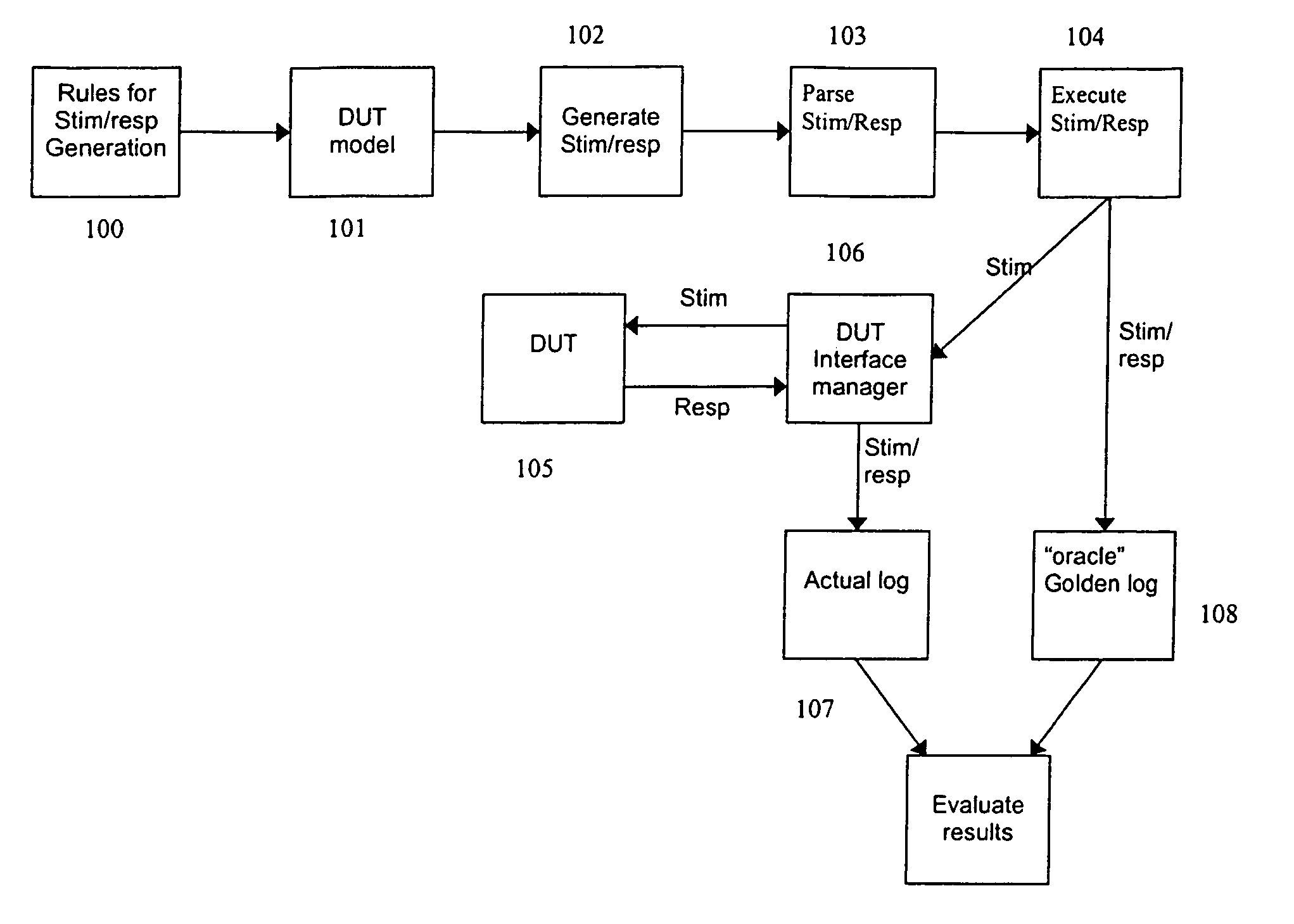
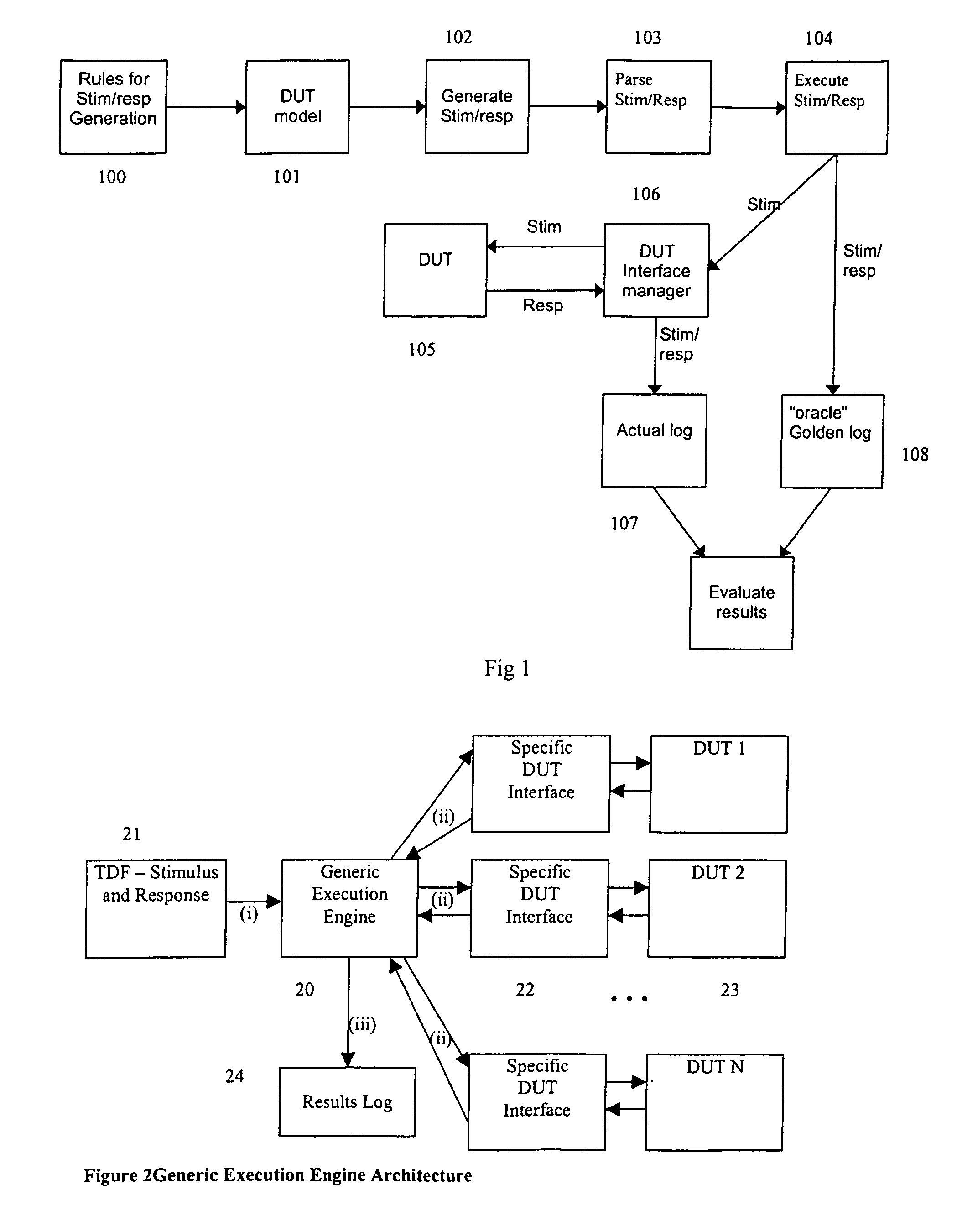
[0118] DUT: Device Under Test. A target embedded device or, an embedded system comprising one or more embedded devices that is the subject of tests. Furthermore, a DUT may comprise one or more embedded systems being the subject of tests.

[0119] Model: An approximation of selected aspects of the behavioural characteristics of a real-world embedded DUT and real world influences on the embedded DUT. A model may use Architectural Level Descriptions (ALD) or Definitions, State Transition Definitions, Message Sequence Charts (MSC's), Hierarchical Message Sequence Charts (HMSC's), Extended Message Sequence Charts (EMSC) and Data Type Definitions to provide an abstract representation of the physical interface, real world environmental influences and constraints upon an embedded DUT.

[0120] Output Port: An output port is used in a model to represent a physical output on the DUT being modelled. The physical outputs of a DUT may ...


PUM


Abstract

An embedded device testing system for comparing actual device under test input/output vector pairs with modelled device under test input/output vector pairs, wherein actual device under test output vectors are sampled in accordance with a predefined timing reference.

Description

RELATED APPLICATIONS [0001] This application claims priority to Australian Provisional Patent Application No. 2004901189, filed 5 Mar. 2004 and Australian Provisional Patent Application No. 2004903723, filed 7 Jul. 2004 both entitled “Testing of Embedded Systems” and, the specifications thereof are incorporated herein by reference in their entirety and for all purposes. FIELD OF INVENTION [0002] The present invention relates to the field of embedded or distributed systems. In one form, the present invention relates to a method and apparatus for the testing of embedded devices. It will be convenient to hereinafter describe the invention in relation to the use of a method and apparatus employing, in part, CASE (Computer Aided Software Engineering) tools to model the behaviour of an embedded device or system referred to herein as a Device Under Test (DUT), however it should be appreciated that the present invention is not limited to that use, only. BACKGROUND ART [0003] Throughout this...

Claims


Application Information

Patent Timeline
Patent Type & Authority Applications(United States)
IPC IPC(8): G01R31/3183
CPCG01R31/31932G01R31/318364G01R31/28G01R31/2803G01R31/3183G01R31/318307
Inventor ACHKAR, HANINEDELKOVSKI, ROBERT DOUGLAS
Owner GARRETT THERMAL SYST LTD
Why Eureka
Try Eureka