Noise Suppression Process And Device

a noise suppression and process technology, applied in the field of noise suppression process and device, can solve the problems of disturbance noise of the pre-echo effect, disturbance noise is clearly audible, and the pre-echo effect disturbance noise is occurrence,

Inactive Publication Date: 2007-12-06
SIEMENS AG
View PDF20 Cites 9 Cited by
  • Summary
  • Abstract
  • Description
  • Claims
  • Application Information

AI Technical Summary

Benefits of technology

[0009] The disadvantage of using these transform codecs is the occurrence of what is known as a “pre-echo effect”. This involves a disturbance noise which is distributed evenly over the entire block length of a transform coder block. A block is understood as a totality of data which is coded together. For transform codecs a typical block length amounts to 40 msec. The disturbance noise of the pre-echo effect is caused b

Problems solved by technology

The disadvantage of using these transform codecs is the occurrence of what is known as a “pre-echo effect”.
This involves a disturbance noise which is distributed evenly over the entire block length of a transform coder block.
The disturbance noise of the pre-echo effect is caused by quantizing errors of transmitted spectral components.
However if one

Method used


Image

  • Noise Suppression Process And Device
  • Noise Suppression Process And Device
  • Noise Suppression Process And Device

Examples


case 2

[0047] The frequency bands A: 0-4000 Hz and B: 4000 Hz-8000 Hz are handled separately (further embodiment): In this case the noise signal is suppressed completely since in the upper frequency band the CELP proportion is zero, and thus the transform codec signal is also limited to the value zero.

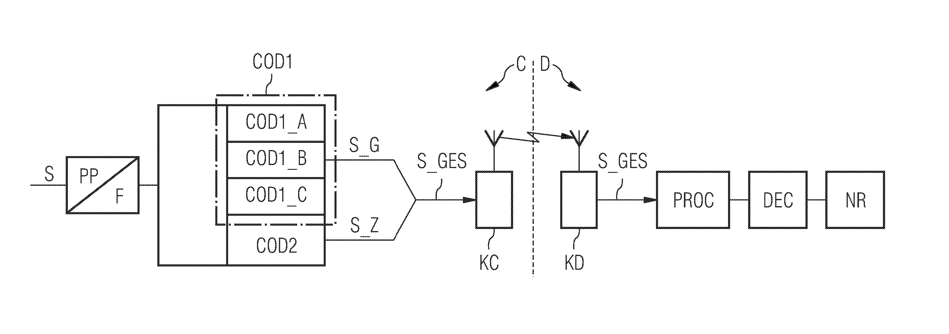
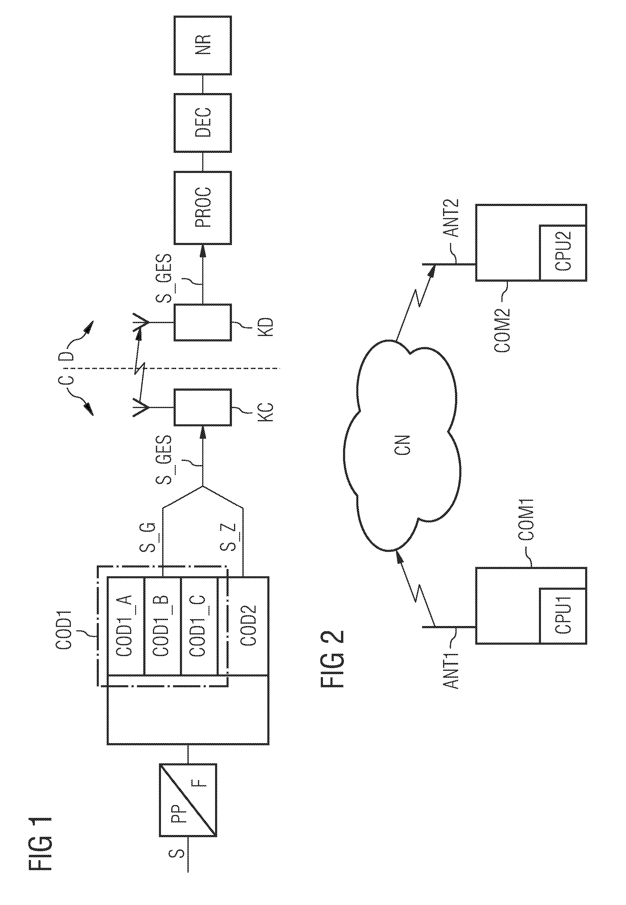
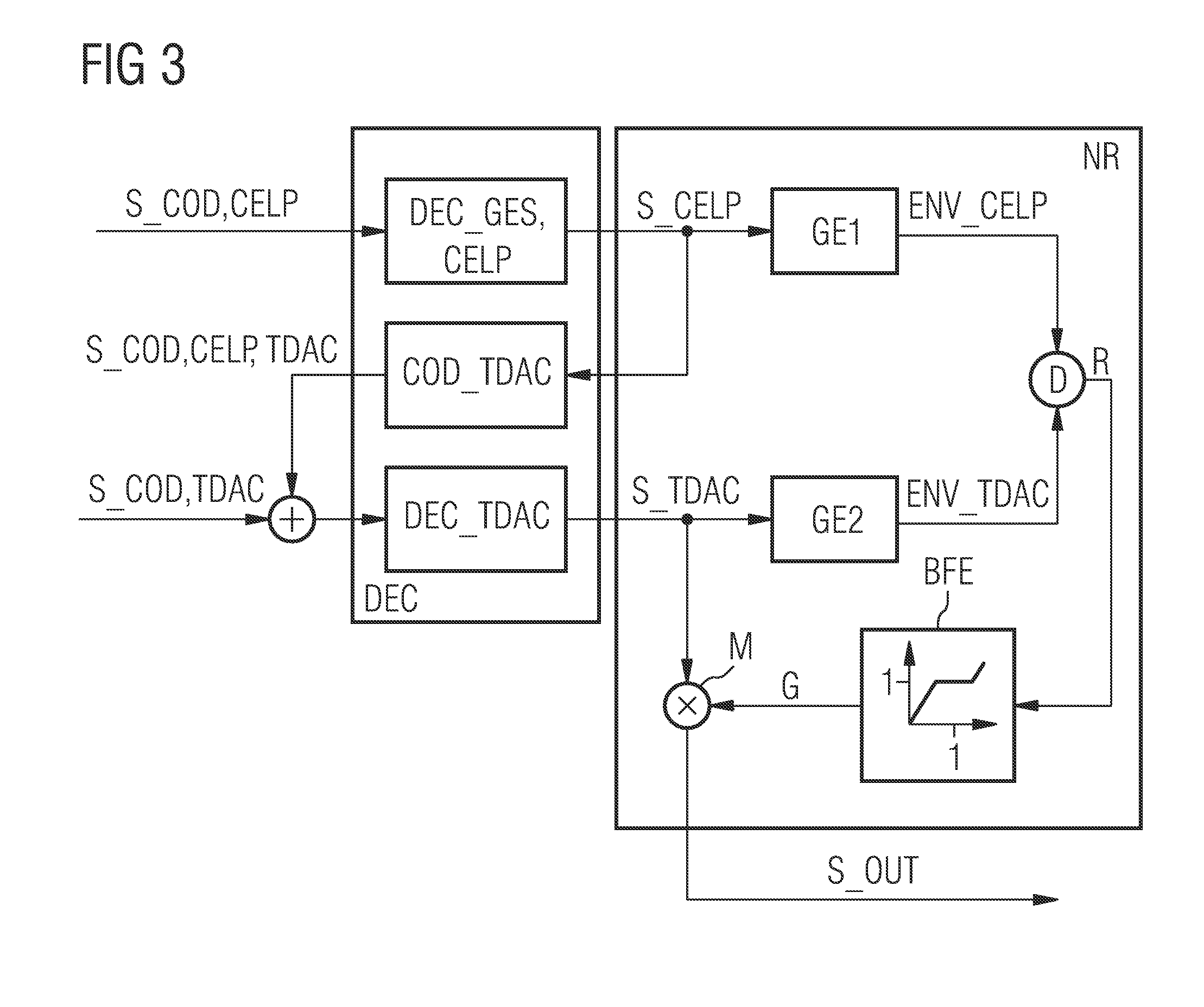
[0048] In FIG. 4 (as in FIG. 3) a decoding device DEC and a noise reduction device NR with the main components for schematic presentation of the execution sequence of a level adaptation or pre-echo reduction can now again be seen. The reader is again referred to FIGS. 1 or 2 for the creation of coded signals or for the transmission to a receiver.

[0049] A CELP-coded signal S_COD,CELP (corresponding to signal contribution S_G) is decoded by means of a full-band CELP decoder DEC_GES,CELP′. The full-band CELP decoder in this case comprises two decoding devices, a first decoding device DEC_FB_A for decoding the signal S_COD,CELP in a first frequency band A and a second decoding device DEC_FB_B f...


PUM


Abstract

In one aspect, a noise suppression process for a decoded signal comprising a first decoded signal portion and a second decoded signal portion is provided. A first energy envelope generating curve and a second energy envelope generating curve of the first signal portion and of the second decoded signal portion are determined. An identification number depending on a comparison of the first and second energy envelope generating curves is formed. An amplification factor which depends on the identification number is derived. Multiplying the second decoded signal portion by the amplification factor, reduces pre-echo and post-echo interference noises.

Description

CROSS REFERENCE TO RELATED APPLICATIONS [0001] This application is the US National Stage of International Application No. PCT / EP2006 / 061537, filed Apr. 12, 2006 and claims the benefit thereof. The International Application claims the benefits of German application No. 102005019863.5 filed Apr. 28, 2005, German application No. 102005028182.6 filed Jun. 17, 2005, and German application No. 102005032079.1 filed Jul. 8, 2005 all of the applications are incorporated by reference herein in their entirety.FIELD OF INVENTION [0002] The invention relates to a method for decoding a signal which has been coded by a hybrid coder. The invention further relates to a device suitably equipped for decoding. BACKGROUND OF INVENTION [0003] Different methods have proved to be especially effective for coding audio signals. Thus what is known as the CELP (Code Excited Linear Prediction) technology has proved especially useful for example for high-quality coding of voice signals which exhibit a good quali...

Claims


Application Information

Patent Timeline
IPC IPC(8): G10L21/00G10L19/02G10L19/025G10L19/24G10L21/02G10L21/0364
CPCG10L19/025G10L21/0364G10L19/24G10L21/0208G10L19/12
Inventor GARTNER, MARTINSCHANDL, STEFAN
Owner SIEMENS AG
Why Eureka
Try Eureka