Economy of motion machine

a technology of motion machines and energy, applied in the direction of hydroelectricity, machines/engines, sea energy generation, etc., can solve the problems of loss of potential energy and very inefficient devices, and achieve the effect of eliminating all consumption and improving the means of producing energy

Inactive Publication Date: 2007-12-13
MCGAHEE VINCENT DEPAUL
View PDF23 Cites 22 Cited by
  • Summary
  • Abstract
  • Description
  • Claims
  • Application Information

AI Technical Summary

Benefits of technology

[0006]The principal objective of the present invention is to improve the means of producing energy and to eliminate entirely the consuming of any and all types of combustible fuels to produce power.

Problems solved by technology

These devices are very inefficient.
Potential energy is lost as water flows past the paddles or turbine blades behind the mass of water causing the paddle or blade to move and before the next paddle or blade is in position to be fully engaged by the flowing water.

Method used


Image

  • Economy of motion machine
  • Economy of motion machine
  • Economy of motion machine

Examples


Embodiment Construction

[0020]Referring more particularly to the drawings wherein similar reference characters designate like parts throughout the several views.

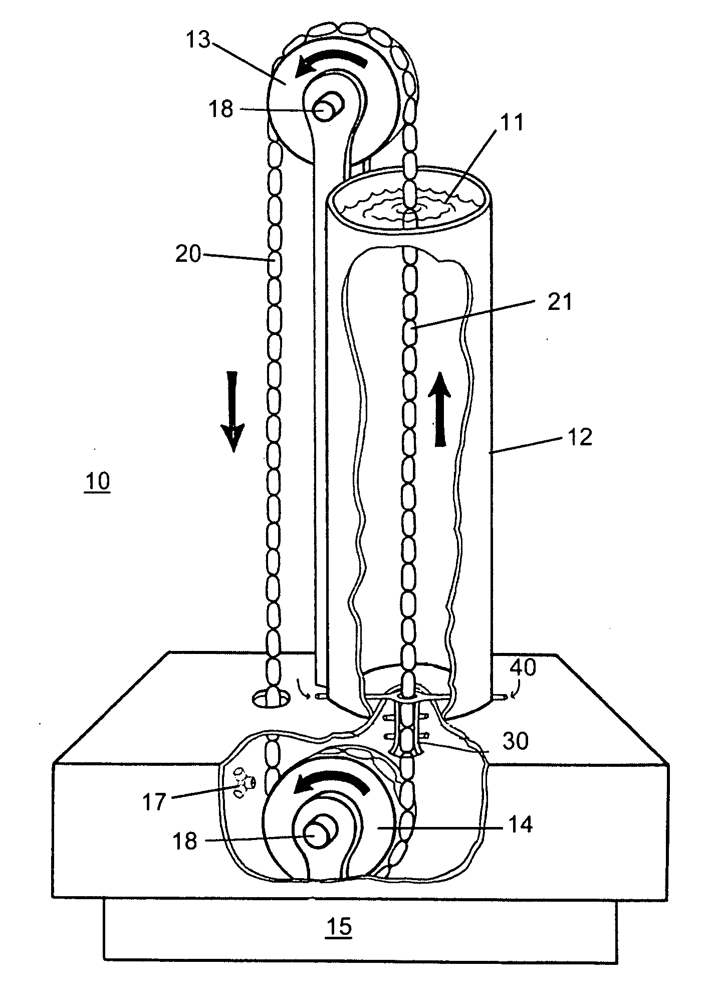
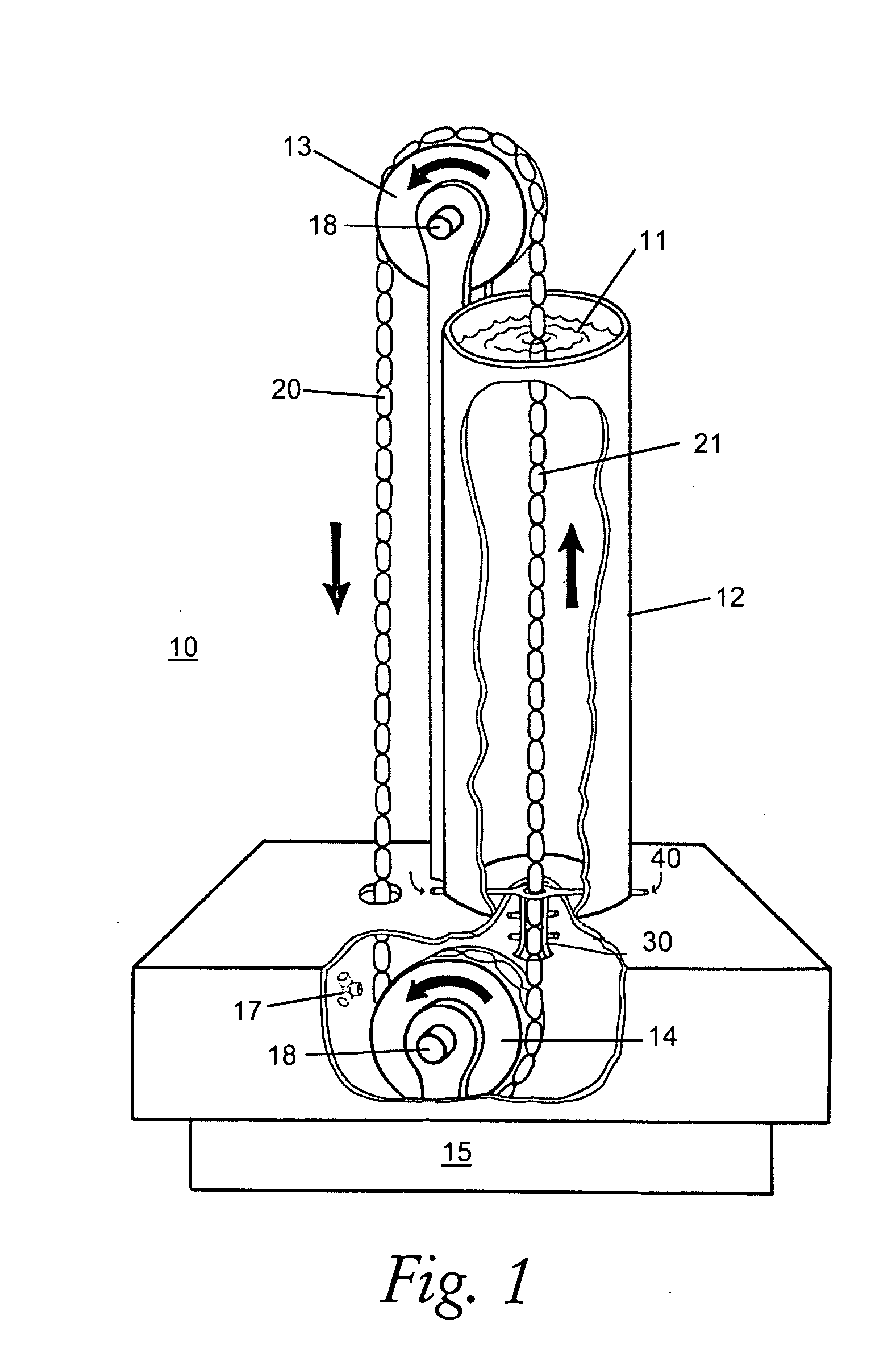
[0021]The Economy of Motion Machine, 10 of FIG. 1, allows the displacing elements 21 forming the displacement chain 20 to move up through the water column 11 as a function of the combined buoyancy of the immersed displacing elements. During this process, the total displacement of water in the upper water tank 12 remains constant. A process clearly unlike other known displacement devices.

[0022]An upper idler wheel 13 guides the displacement chain in a 180° arc, allowing the mass of the displacing elements 21 to force the displacement chain 20 down on one side of the upper idler wheel as the buoyancy of the displacing elements on the other side pulls the displacement chain around the lower idler wheel 14 and up through the water column 11. This goes on constantly or as long as desired.

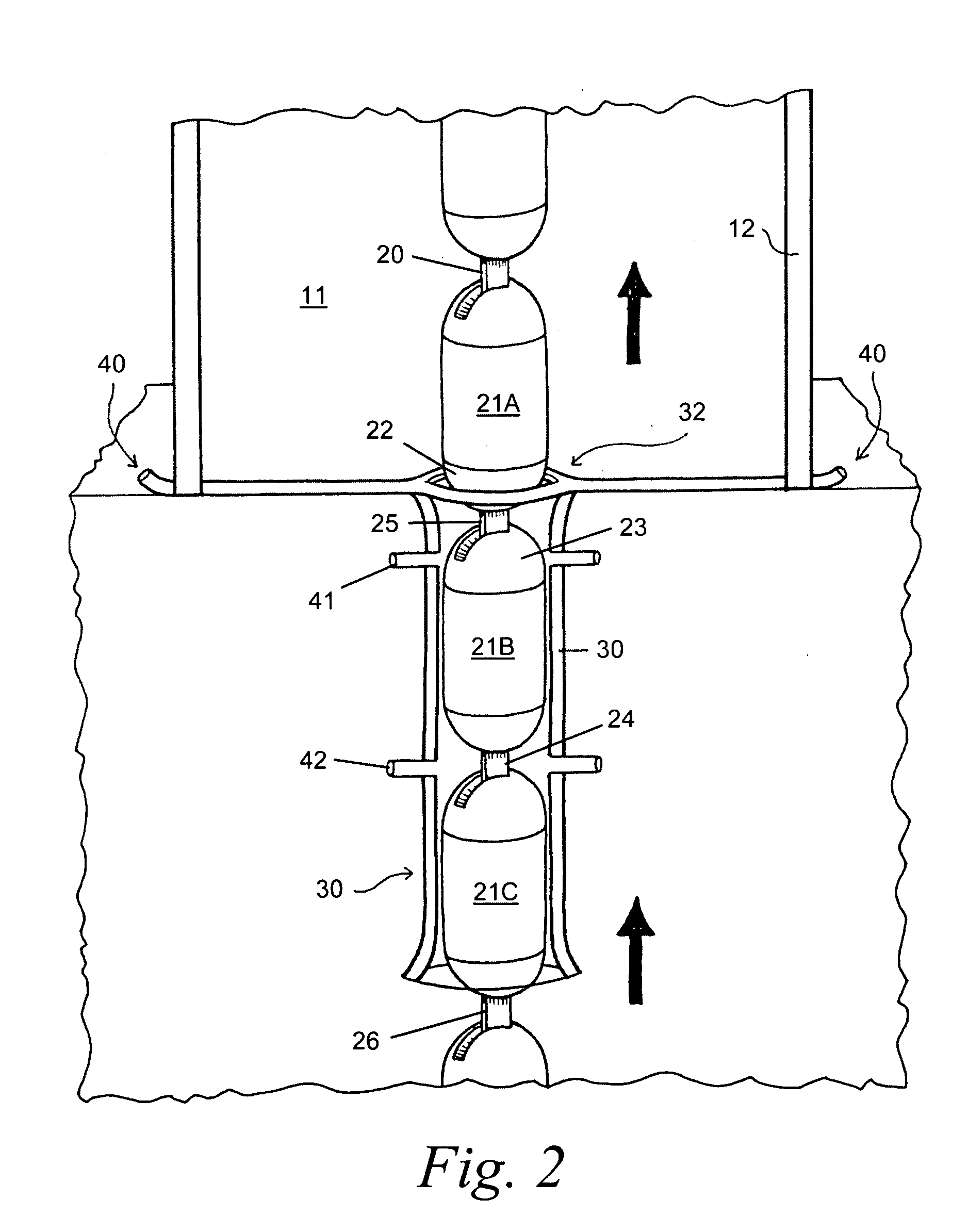
[0023]Each displacing element 21 of the displacement chain 20 ente...


PUM


Abstract

The invention is a method and apparatus for extracting power from a buoyant source within a contained column of liquid. It is comprised of an endless chain of movable buoyant objects, a means to convert the movement of the chain into useful work and a tank filled with a constant volume column of water. The buoyant objects comprising the chain sequentially enter the bottom of the water column, move up through the column and emerge at the surface. The emerging buoyant objects leave the tank and are directed to the tank bottom were each buoyant object repeats the cycle. As the chain of buoyant objects cycle through the water column, the volume of water remains constant, with one buoyant object of the chain entering the bottom of the water column as one is exiting at the top surface. The movement of the chain is a function of the buoyancy of the buoyant objects and the movement is converted to work by any conventional means using a rotary drive or linear escapement motor.

Description

BACKGROUND OF THE INVENTION[0001]1. Field of the Invention[0002]The invention relates to a method and apparatus for producing energy without creating pollution or using any known consumables currently employed to produce energy. It is a means and apparatus for extracting energy as a function of the relative density between an object and a fluid, e.g., displacement of water. It is a more efficient way of extracting potential energy from a mass of water than the ancient water wheel or modern turbine.[0003]2. Discussion of the Related Art[0004]Water has been used by man for centuries to do work and create energy. This has always been accomplished as a function of gravity induced motion of the water. The earliest known devices were simple water wheels which have evolved into modern turbines used in hydroelectric systems employing massive dams. These devices are very inefficient. Potential energy is lost as water flows past the paddles or turbine blades behind the mass of water causing t...

Claims


Application Information

Patent Timeline
Patent Type & Authority Applications(United States)
IPC IPC(8): F03B13/18F03B17/02
CPCF03B17/04Y02E10/38Y02E10/20Y02E10/30
Inventor MCGAHEE, WELBOURNE
Owner MCGAHEE VINCENT DEPAUL
Why Eureka
Try Eureka