
Method, Computer Program Product and Arrangement for Controlling the Milking by a Milking Machine

Active Publication Date: 2007-12-13
DELAVAL HLDG AB
View PDF4 Cites 7 Cited by
  • Summary
  • Abstract
  • Description
  • Claims
  • Application Information

AI Technical Summary

Benefits of technology

[0009] It is therefore an object of the present invention to provide a method for controlling the milking by a milking machine, by which method the milking production is increased, and the animal treatment is improved.
[0010] It is a further object of the invention to provide such a method, which is accurate, efficient, reliable, of low cost, and easy to implement.
[0015] By means of the present invention the overall milk production is optimized. The milk production can be maximized, while the animal care is maintained or even improved. Each milking animal is not exposed to higher levels of vacuum than necessary to obtain a given milk flow. As compared -to the use of a fixed-constant milking vacuum for all milking animals, the present invention provides for higher milk throughput since higher flows of milk can be obtained for some milking animals by means of increasing the milking vacuum, and thus the milking times are shortened for these milking animals. For other milking animals, the milk flows can roughly be maintained, while the vacuum levels are decreased, to thereby obtain a more gentle treatment of the teats while maintaining the level of the milk production.

Problems solved by technology

While the above references disclose different methods and means for improving the milking, they all fail to disclose how to obtain animal individual milking, which is optimized for each single milking animal.

Method used


Image

  • Method, Computer Program Product and Arrangement for Controlling the Milking by a Milking Machine
  • Method, Computer Program Product and Arrangement for Controlling the Milking by a Milking Machine
  • Method, Computer Program Product and Arrangement for Controlling the Milking by a Milking Machine

Examples


Embodiment Construction

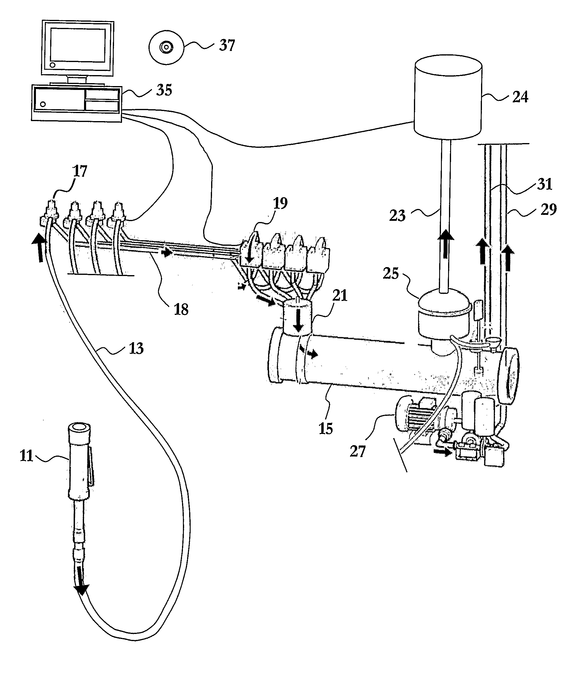
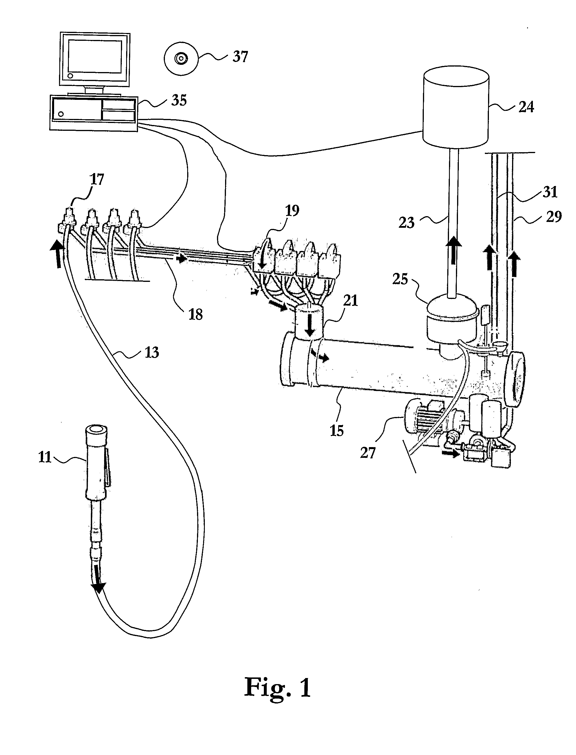
[0021]FIG. 1 illustrates some of the main components of an automated milking system for cows wherein the present invention is implemented. The automated milking system comprises a milking machine having four teat cups 11, of which only one is illustrated for sake of simplicity. Each teat cup 11 is connected to a respective milk tube 13, which in turn is connected to an end unit 15 via a respective valve or regulator 17, a respective milk conduit 18, a respective flow meter 19, optionally a respective conductivity meter or other measuring device such as an infrared spectrometer device (not shown), and a common milk meter 21. The end unit 15 is connected to a vacuum source 24 via a milk / air separator 25 and a vacuum supply conduit 23. The vacuum source 24 may be a vacuum pump of the rotary vane type, but is preferably a frequency controlled pump.

[0022] During milking of the teats of a cow, the teat cups are attached to the teats of a cow by a robot or manually, and vacuum is supplied...


PUM


Abstract

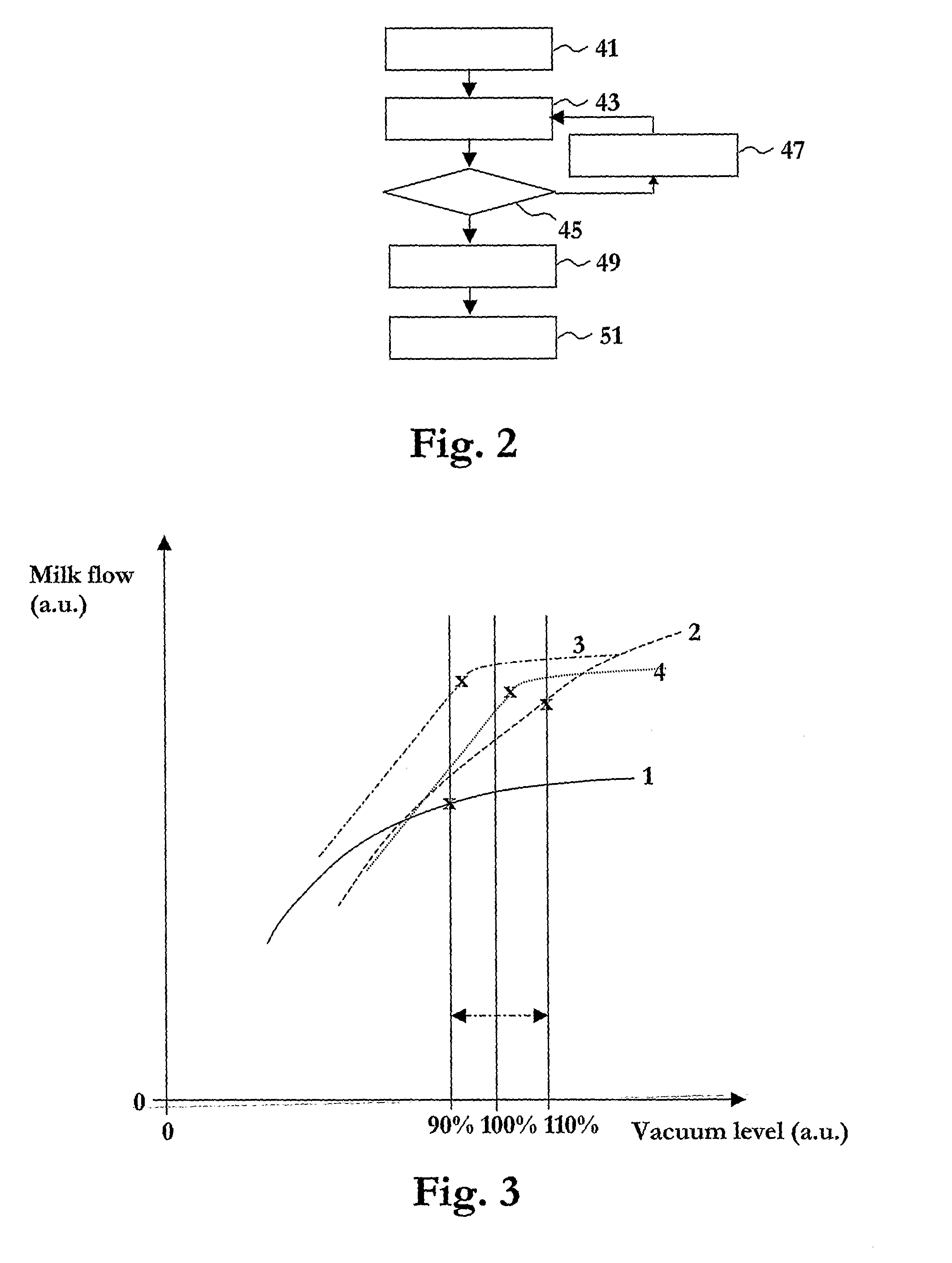
A method for controlling he milking by a milking machine comprises the steps of: (i) controlling (47) a milking vacuum so that the milking vacuum is varied through the vacuum levels of a given range, while a milking animal is milked by the aid of the milking vacuum; (ii) monitoring (43) a milk flow from the milking animal during the variation of the vacuum levels; (iii) setting (49) the milking vacuum to the lowest vacuum level of the given range, for which the milk flow from the milking animal is at least a given fraction of the highest milk flow monitored while the milking vacuum is varied; and (iv) keeping (51) the milking vacuum at the set vacuum level during a following part of the milking of the milking animal.

Description

TECHNICAL FIELD OF THE INVENTION [0001] The present invention relates generally to dairy farming and to milking of dairy animals therein. Particularly, the invention relates to a method for controlling the milking by a milking machine, to a computer program product for carrying out the method when being run on a computer, and to an arrangement for controlling and monitoring the milking at a milking station. DESCRIPTION OF RELATED ART AND BACKGROUND OF THE INVENTION [0002] In modern dairy farm industry there are continuous research and development activities in order to improve the efficiency of various activities such as machine milking, which, inter alia, involves increased milk yield and reduced milking time, while, is naturally, ethical aspects as well as animal care are considered. [0003] Machine milking, as known in the art, generally utilizes teat cups and vacuum sources to perform the milking function. In such systems each teat is contained within a teat cup having a teat rec...

Claims


Application Information

Patent Timeline
IPC IPC(8): A01J5/007A01J
CPCA01J5/007
Inventor SCHUSTER, ANDERS
Owner DELAVAL HLDG AB
Learn More