Consumable downhole tools

a tool and consumable technology, applied in the direction of borehole/well accessories, sealing/packing, insulation, etc., can solve the problems of inconsistent yield, time-consuming and expensive operation of milling and drilling,

Inactive Publication Date: 2007-12-13
HALLIBURTON ENERGY SERVICES INC
View PDF99 Cites 52 Cited by
  • Summary
  • Abstract
  • Description
  • Claims
  • Application Information

AI Technical Summary

Problems solved by technology

Nevertheless, milling and drilling continues to be a time consuming and expensive operation.
This method, however, sometimes yields inconsistent results.

Method used


Image

  • Consumable downhole tools
  • Consumable downhole tools
  • Consumable downhole tools

Examples


Embodiment Construction

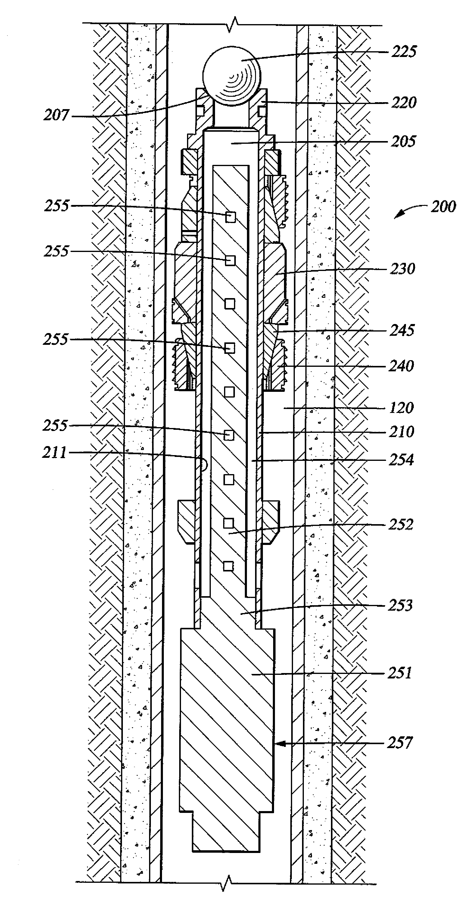
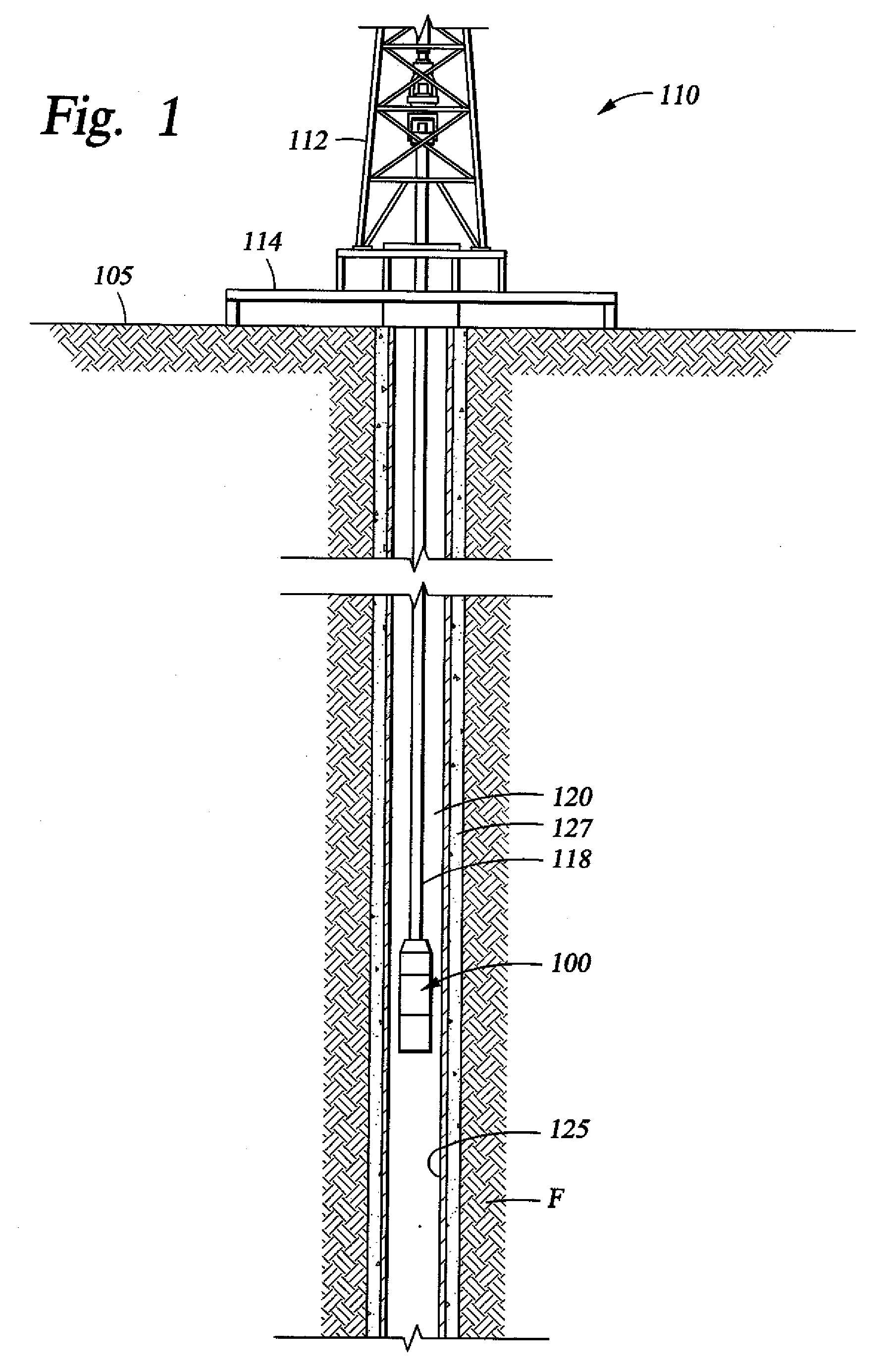
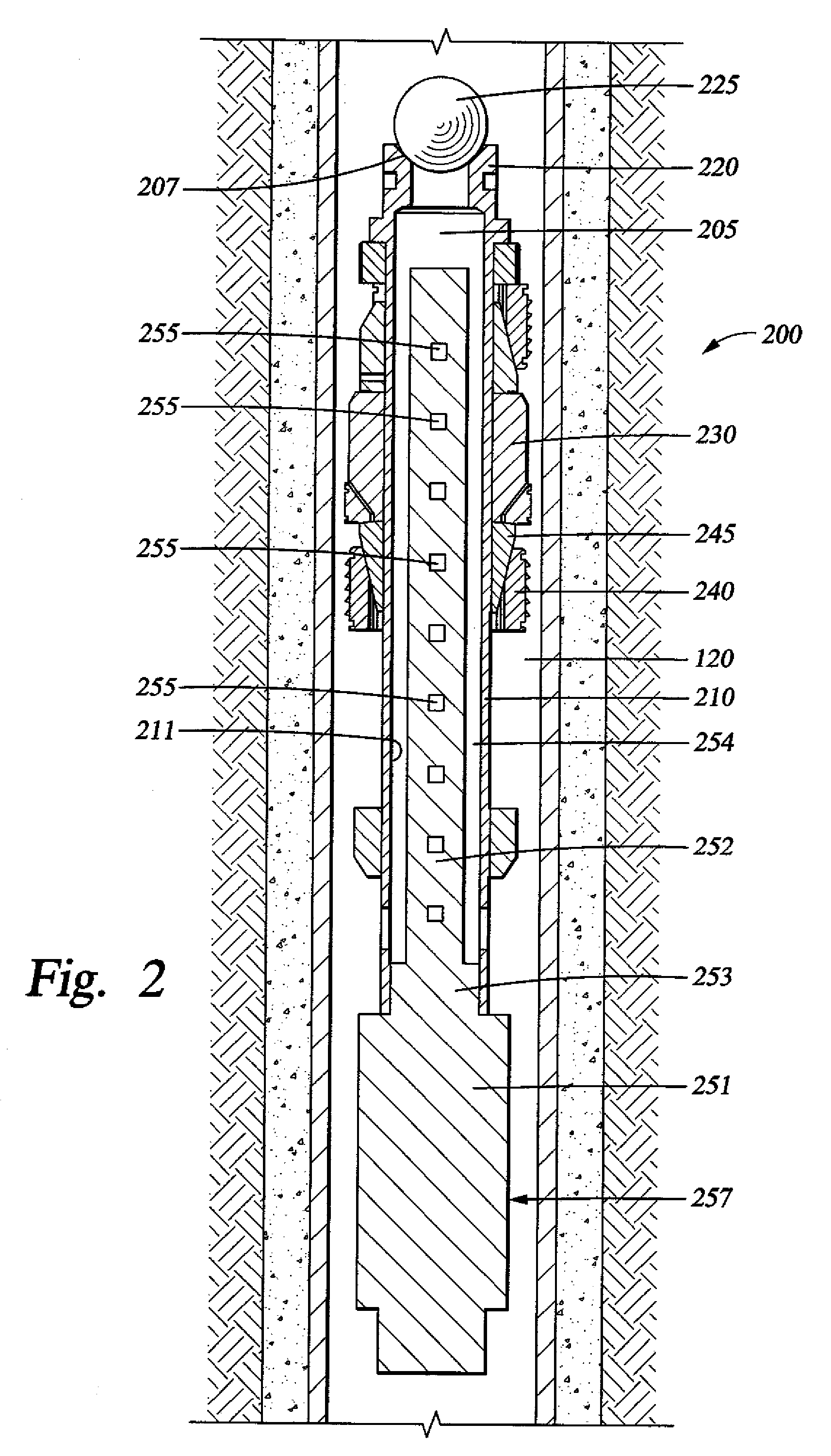
[0015]FIG. 1 schematically depicts an exemplary operating environment for a consumable downhole tool 100. As depicted, a drilling rig 110 is positioned on the earth's surface 105 and extends over and around a well bore 120 that penetrates a subterranean formation F for the purpose of recovering hydrocarbons. At least the upper portion of the well bore 120 may be lined with casing 125 that is cemented 127 into position against the formation F in a conventional manner. The drilling rig 110 includes a derrick 112 with a rig floor 114 through which a work string 118, such as a cable, wireline, E-line, Z-line, jointed pipe, or coiled tubing, for example, extends downwardly from the drilling rig 110 into the well bore 120. The work string 118 suspends a representative consumable downhole tool 100, which may comprise a frac plug, a bridge plug, a packer, or another type of well bore zonal isolation device, for example, as it is being lowered to a predetermined depth within the well bore 12...


PUM


Abstract

A downhole tool having a body or structural component comprises a material that is at least partially consumed when exposed to heat and a source of oxygen. The material may comprise a metal, such as magnesium, which is converted to magnesium oxide when exposed to heat and a source of oxygen. The downhole tool may further comprise a torch with a fuel load that produces the heat and source of oxygen when burned. The fuel load may comprise a flammable, non-explosive solid, such as thermite.

Description

CROSS-REFERENCE TO RELATED APPLICATIONS[0001]None.STATEMENT REGARDING FEDERALLY SPONSORED RESEARCH OR DEVELOPMENT[0002]Not applicable.REFERENCE TO A MICROFICHE APPENDIX[0003]Not applicable.FIELD OF THE INVENTION[0004]The present invention relates to consumable downhole tools and methods of removing such tools from well bores. More particularly, the present invention relates to downhole tools comprising materials that are burned and / or consumed when exposed to heat and an oxygen source and methods and systems for consuming such downhole tools in situ.BACKGROUND[0005]A wide variety of downhole tools may be used within a well bore in connection with producing hydrocarbons or reworking a well that extends into a hydrocarbon formation. Downhole tools such as frac plugs, bridge plugs, and packers, for example, may be used to seal a component against casing along the well bore wall or to isolate one pressure zone of the formation from another. Such downhole tools are well known in the art....

Claims


Application Information

Patent Timeline
Patent Type & Authority Applications(United States)
IPC IPC(8): E21B36/00E21B29/02
CPCE21B17/06E21B31/002E21B29/02E21B23/06
Inventor SWOR, LORENSTARR, PHILLIPSMITH, DON R.WILKINSON, BRIAN K.
Owner HALLIBURTON ENERGY SERVICES INC
Why Eureka
Try Eureka