Brake disc assembly and method of construction

Inactive Publication Date: 2007-12-13
FEDERAL MOGUL WORLD WIDE
View PDF32 Cites 30 Cited by
  • Summary
  • Abstract
  • Description
  • Claims
  • Application Information

AI Technical Summary

Benefits of technology

[0008]In view of the above, there exists a need for a brake disc assembly that is both lightweight and resistant to the heat-related problems described above. Further, there is a need for a brake disc assembly that provides better performance ove

Problems solved by technology

These frictional forces generate a considerable amount of heat that tends to be absorbed by the rotor and causes its temperature to rise.
As the temperature of the rotor increases, the braking performance may be adversely affected, e.g., the coefficient of friction between the rotor and the brake pads decreases as the temperature of the rotor increases.
Even with this conventional construction, poor performance due to high temperatures remains a problem.
Further, prior art brake disc assemblies are quite heavy.
In currently used systems, the rotor is

Method used


Image

  • Brake disc assembly and method of construction
  • Brake disc assembly and method of construction
  • Brake disc assembly and method of construction

Examples


Embodiment Construction

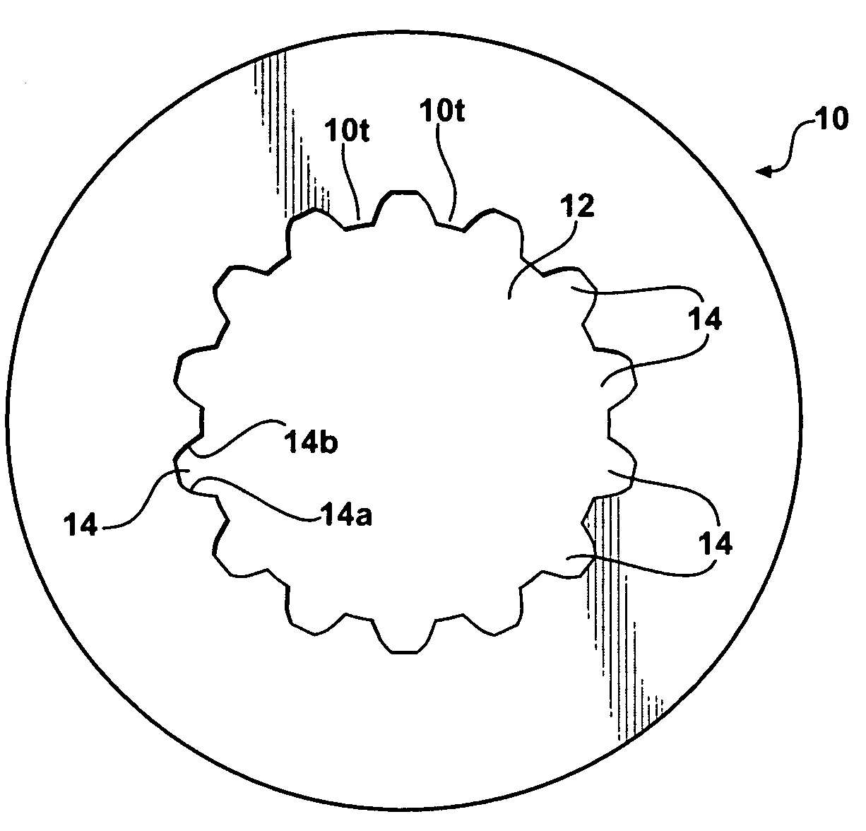
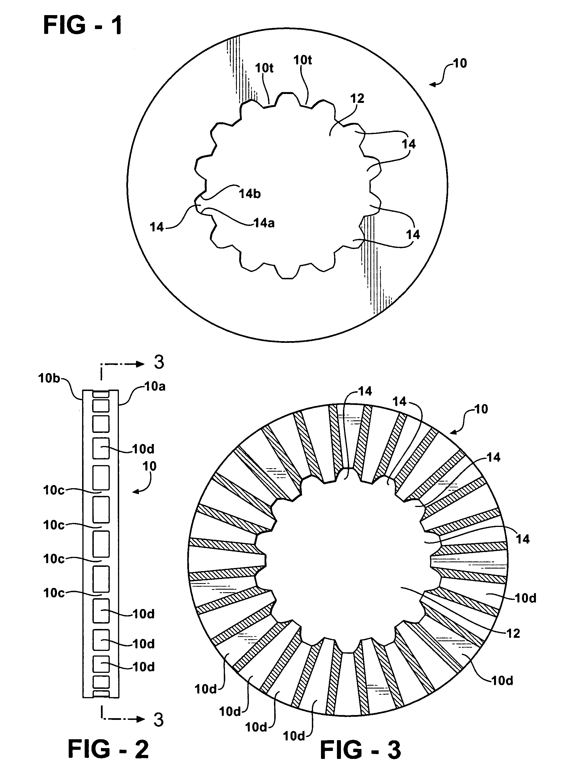
[0023]Referring to FIG. 1, a rotor portion 10 of a brake disc assembly 100 according to one embodiment of the present invention is disclosed. The rotor 10 includes an opening 12 disposed in its interior. This opening 12 is capable of receiving and securing a hat assembly 50, as described more fully below. The opening 12 includes a plurality of radial recesses 14 extending in an outwardly direction from the center of the rotor 10. These radial recesses 14 include first and second sides or side portions 14a and 14b. In a preferred embodiment, these side portions have the shape of an involute with respect to the curved projections of the hat assembly, as described more fully below. Between each of the radial recesses 14 is a rotor tooth 10t.

[0024]FIG. 2 is a side-view of rotor 10. Rotor 10 is comprised of two annular portions 10a and 10b with a plurality of ribs or vanes 10c that connect the two annular portions 10a and 10b, as is well known in the art. While the discussion below is d...


PUM


Abstract

A brake disc assembly comprises a rotor and a hat assembly. The hat assembly is comprised of two hat portions, each having a plurality of curved projections. The curved projections interact with radial recesses formed in the rotor to ensure a secure connection between the hat assembly and the rotor over a wide range of operating conditions.

Description

RELATED APPLICATIONS[0001]None.STATEMENT REGARDING FEDERALLY SPONSORED RESEARCH[0002]None.TECHNICAL FIELD[0003]The present invention relates to a brake disc assembly and a method for assembling the same that provides improved performance over a wide range of operating conditions.BACKGROUND OF THE INVENTION[0004]Brake disc assemblies are well-known in the art and are commonly used, for example, as a component of braking systems of motor vehicles. A brake disc or rotor is arranged to rotate with a member, such as a wheel or axle of a vehicle. Such a rotor provides two oppositely-facing annular friction surfaces that, in the operation of the brake, are engaged by blocks of friction material to decelerate the rotor and hence the member. Two of the friction material blocks are moved (usually by hydraulic means) towards one another into contact with the two friction surfaces so that frictional forces occur, which slows the rotation of the rotor, and hence the member. These frictional forc...

Claims


Application Information

Patent Timeline
IPC IPC(8): F16D65/12
CPCF16D65/123F16D2065/1368F16D2065/1348F16D2065/1328
Inventor HAMPTON, KEITH
Owner FEDERAL MOGUL WORLD WIDE
Why Eureka
Try Eureka