

Variably responsive photosensor
- Summary
- Abstract
- Description
- Claims
- Application Information
AI Technical Summary
Benefits of technology
Problems solved by technology
Method used
Image

Examples
second embodiment
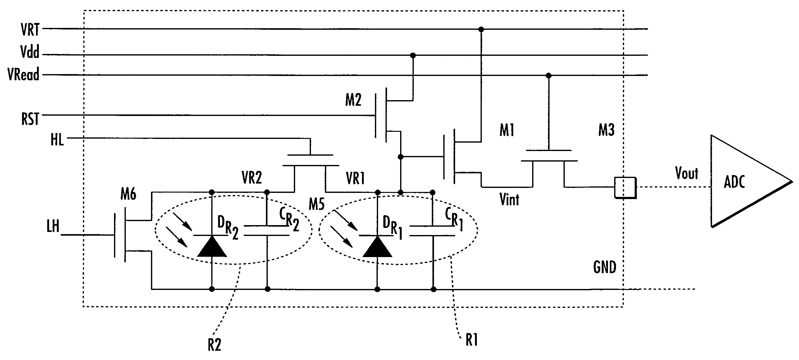
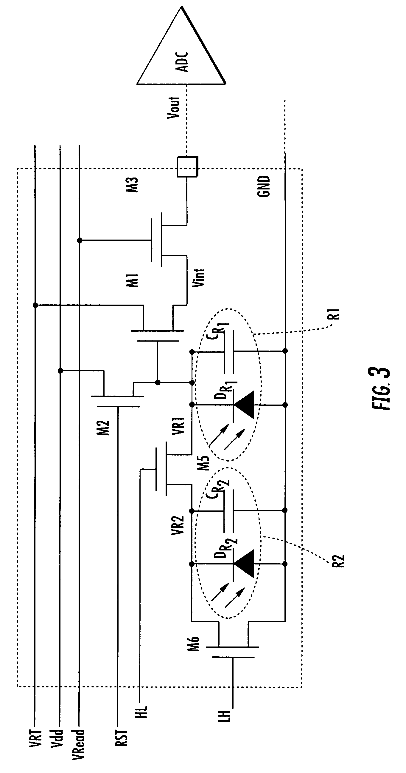
[0045]TABLE 1 lists the operating parameters of the variable response photosensor of FIGS. 9 and 10.
TABLE 1LightActiveLevelCapacitanceSensitivityRegionsHL1LH1HL2LH2HL3LH3HighHighLow1, 2, 3, 4101010MediumMediumMedium1, 3, 4011010HighHighLowMediumMediumMedium1, 4010110LowLowHighLowLowHigh1010101
[0046]The following description will provide a brief overview of the concept underlying the variable response photosensor. This will be followed by a more detailed explanation of a first embodiment of the variable response photosensor comprising only two photosensitive regions. In particular, the discussion will focus on the structure of the first embodiment of the variable response photosensor and its operation with reference to the electric fields developed therein. The detailed description will finish with a description of a second embodiment of the variable response photosensor comprising multiple photosensitive regions.
[0047]The following descriptions are based on an embodiment comprising ...
first embodiment
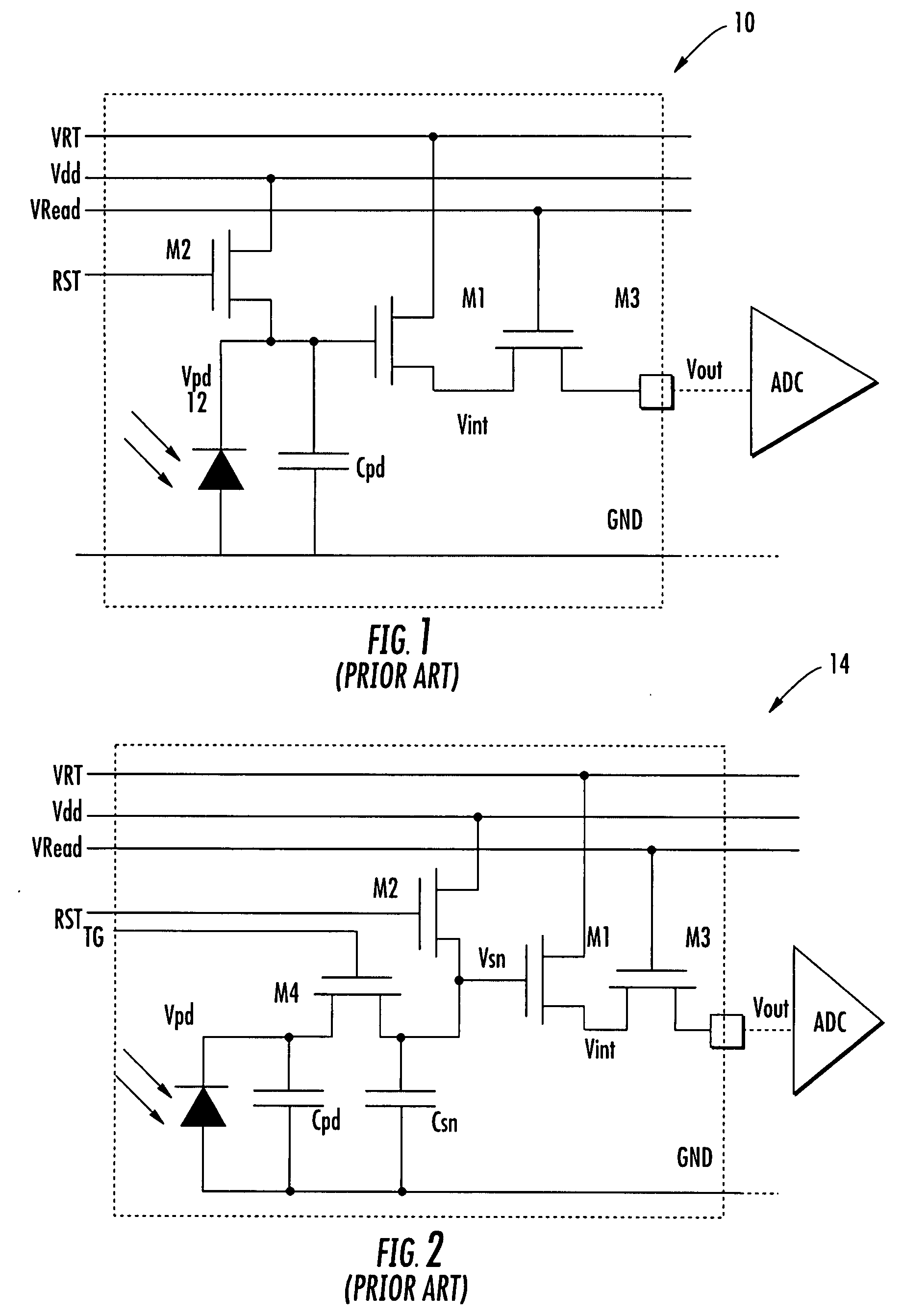
[0058]the variable response photosensor comprising two photosensitive regions will now be discussed. In terms of structural aspects, the isolation, at low light levels, of the diode and capacitance of the second photosensitive region (i.e., Dp2 / Cpd2) from the sense node (M1) by the transistor M6 is best explained by examining an exemplary pixel employing the variable response photosensor in FIG. 4 whose internal semiconductor structure is shown in FIG. 5. It will be noted that the position and size of transistors M1 to M6 depicted in FIG. 4 are provided for illustration purposes only. In particular, the actual size and layout of the transistors may be altered to satisfy individual system performance requirements (e.g., pixel size, noise, speed, power consumption, etc.).
[0059]Referring to FIG. 4, let a pixel 30 comprise a first variable response photosensor (PD1) and a second variable response photosensor (PD2). Let the first variable response photosensor (PD1) be divided into two ph...
PUM
| Property | Measurement | Unit |
|---|---|---|
| Electric potential / voltage | aaaaa | aaaaa |
| Photosensitivity | aaaaa | aaaaa |
Abstract
Description
Claims
Application Information