Dimmer switch with adjustable high-end trim

a dimmer switch and high-end technology, applied in the direction of switches, contact mechanisms, switches, etc., can solve the problem of no user-accessible means for users to be able to change the high-end trim

Inactive Publication Date: 2007-12-13
LUTRON TECH CO LLC
View PDF10 Cites 80 Cited by
  • Summary
  • Abstract
  • Description
  • Claims
  • Application Information

AI Technical Summary

Benefits of technology

[0009]In one embodiment of the present invention, a load control device with an adjustable high-end trim comprises a user-accessible means for reducing the high-end trim of the load control device from a first level to a second level lower than the first level, the user-accessible means for reducing having substantially no affect upon the low-end trim of the load control device.

Problems solved by technology

Prior art dimmer switches typically have fixed high-end trims and provide no user-accessible means for a user to be able to change the high-end trim.

Method used


Image

  • Dimmer switch with adjustable high-end trim
  • Dimmer switch with adjustable high-end trim
  • Dimmer switch with adjustable high-end trim

Examples


first embodiment

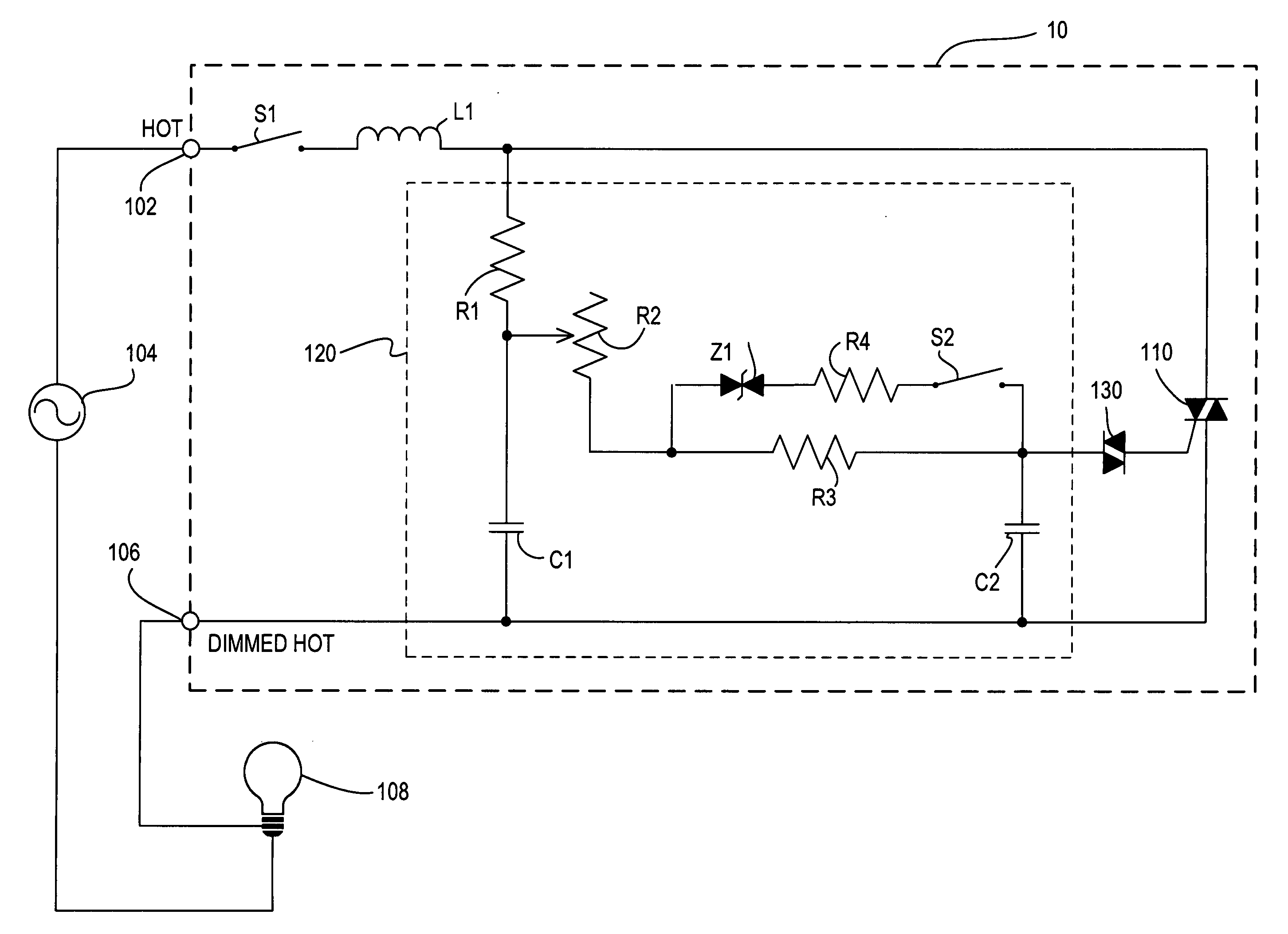
[0028]FIG. 3 is a simplified electrical schematic diagram of the dimmer switch 10 according to the present invention. The dimmer switch 10 includes a hot terminal 102 that is connected to an AC power source 104, and a dimmed hot terminal 106 that is connected to a lighting load 108, such as an electric lamp. The dimmer switch 10 includes a switch S1 connected to the hot terminal 102, a choke L1 connected in series with the switch S1, and a triac 110 connected in series between the choke L1 and the dimmed hot terminal 106. The triac 110 may alternatively be replaced by any suitable bidirectional switch, such as, for example, a field-effect transistor (FET) or an insulated gate bipolar junction transistor (IGBT) in a rectifier bridge, two FETs in anti-series connection, two IGBTs in anti-series connection, or a pair of silicon-controlled rectifiers. The switch S1 is the electrical representation of the rocker switch 12 of the user interface of the dimmer switch 10. When the switch S1 ...

second embodiment

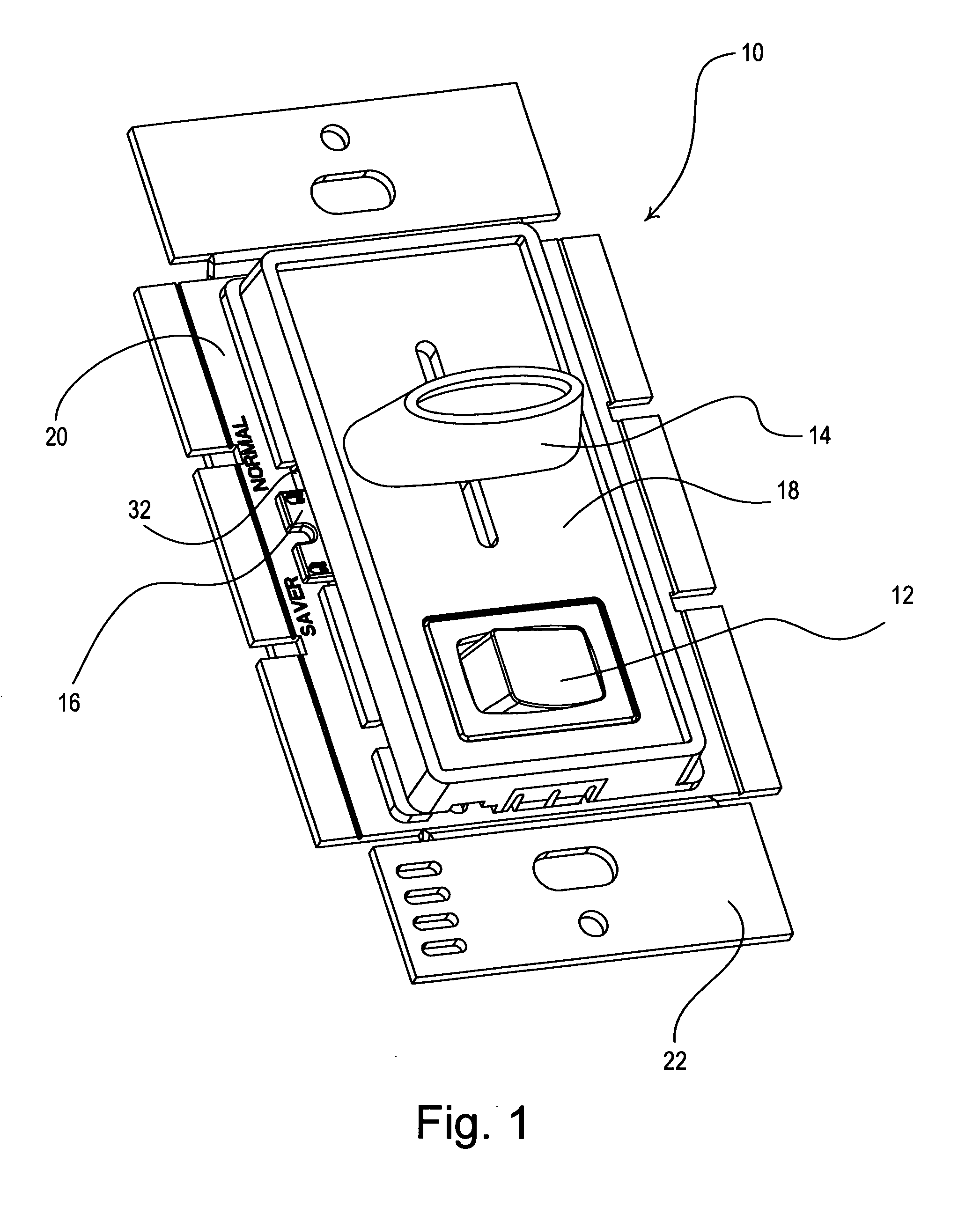
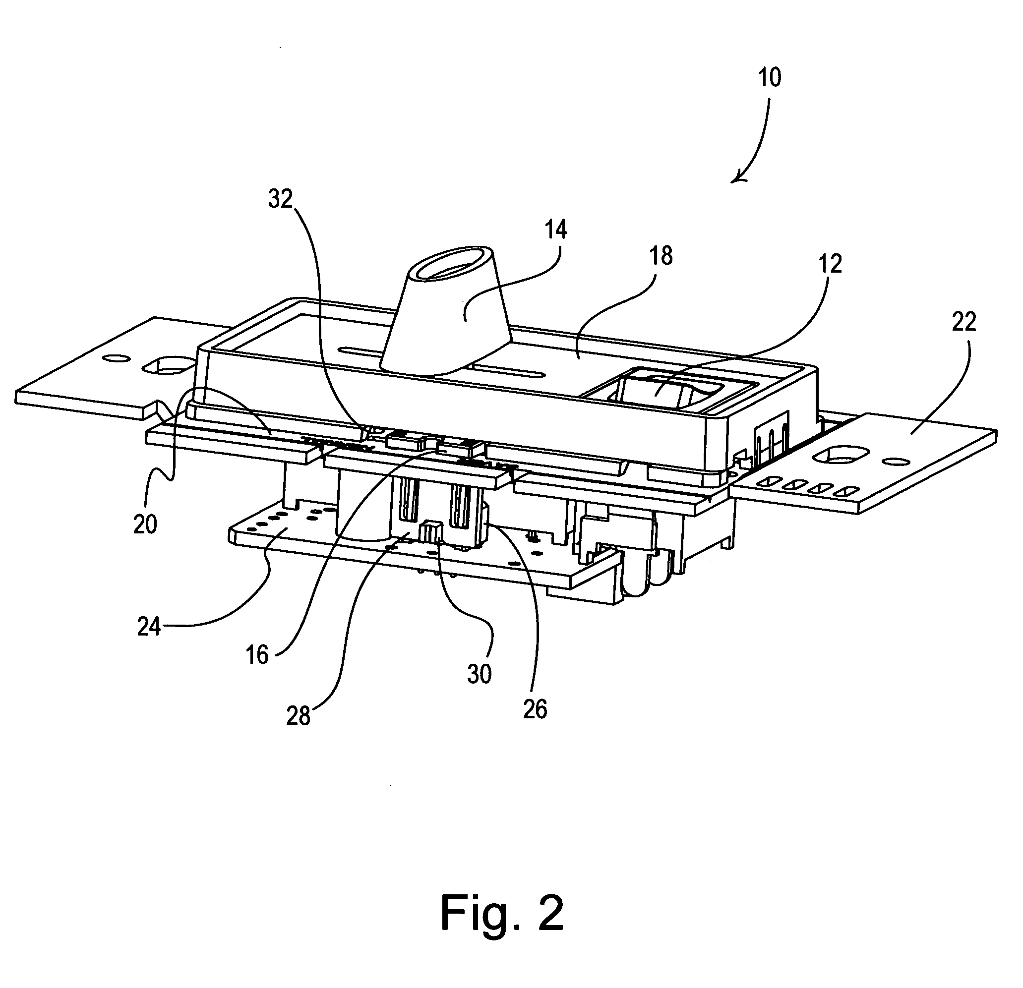
[0040]FIG. 5 is a simplified electrical schematic diagram of a dimmer switch 200 according to the present invention. Rather than including the switch S2, the dimmer switch 200 comprises a potentiometer R5 for adjusting the high-end trim. The potentiometer R5 has a wiper lead that is connected to the second lead of the resistor R4 and a second lead connected to the junction of the resistor R3, the capacitor C2, and the diac 130. Preferably, potentiometer R5 comprises an adjustment member, such as a slider control or a rotary knob, which is provided in an opening in the yoke 22 or between the bezel 18 and the yoke 22 (e.g., the opening 32 shown in FIGS. 1 and 2). The potentiometer R5 preferably has a value that can be varied from a minimum resistance (e.g., approximately 0Ω) up to a maximum value of about 1 MΩ. When the resistance of the potentiometer R5 is substantially 0Ω, the dimmer 200 operates at the first nominal high-end trim level (as does the dimmer 10 of FIG. 3 when the swit...

third embodiment

[0041]FIG. 6 is a simplified electrical schematic diagram of a dimmer switch 300 according to the present invention. The dimmer switch 300 comprises a multi-position switch S2′, having four (4) positions A, B, C, D. Three resistors R6A, R6B, R6C are coupled between the transient voltage suppressor Z1 and the multi-position switch S2′. The transient voltage suppressor Z1 is coupled in series with the first resistor R6A, the second resistor R6B, and the third resistor R6C when the switch S2′ is in the first position A, the second position B, and the third position C, respectively. When the switch S2′ is in the fourth position D, the series combination of the transient voltage suppressor Z1 and the resistor R4 is simply coupled in parallel with the resistor R3. The first resistor R6A has a first resistance, for example, 63 kΩ. The second resistor R6B has a second resistance, smaller than the first resistance, for example, 56 kΩ. The third resistor R6C has a third resistance, smaller th...


PUM


Abstract

A dimmer switch has a user adjustable high-end trim. The dimmer switch includes a bidirectional semiconductor switch, such as a triac, for controlling the amount of power delivered from a source of alternating current power to a lighting load, such as an electric lamp. A user-adjustable timing circuit controls the conduction time of the triac from a minimum time to a maximum time. The maximum possible conduction time of the triac is the high-end trim. The minimum possible conduction time of the triac is the low-end trim. The timing circuit includes a user-accessible switch that allows a user to reduce the high-end trim from a first nominal level to a second reduced level, lower than the first level, without substantially affecting the low-end trim. The switch allows a user to switch a transient voltage suppressor into and out of parallel connection with a resistor that is part of an RC timing circuit for the triac. The dimmer switch advantageously uses less energy and the lifetime of the lamp is extended when the second reduced level of the high-end trim is selected.

Description

RELATED APPLICATIONS[0001]This application claims priority from commonly-assigned U.S. Provisional Patent Application Ser. No. 60 / 812,337, filed Jun. 8, 2006, entitled DIMMER WITH ADJUSTABLE HIGH-END TRIM, the entire disclosure of which is hereby incorporated by reference.BACKGROUND OF THE INVENTION[0002]1. Field of the Invention[0003]The present invention relates to load control devices for controlling the amount of power delivered to an electrical load, specifically a dimmer switch that controls the intensity of a lighting load. More particularly, the invention relates to a dimmer switch having a user-accessible switch for adjusting a high-end trim of the dimmer switch.[0004]2. Description of the Related Art[0005]A conventional wall-mounted load control device is mounted to a standard electrical wall box and is coupled between a source of alternating-current (AC) power (typically 50 or 60 Hz line voltage AC mains) and an electrical load. Standard load control devices, such as dimm...

Claims


Application Information

Patent Timeline
Patent Type & Authority Applications(United States)
IPC IPC(8): F02P7/03
CPCH05B39/085H01H23/02
Inventor GEHMAN, JACKSON
Owner LUTRON TECH CO LLC
Why Eureka
Try Eureka