Multi-frequency antenna with dual loops

Active Publication Date: 2007-12-13
ADVANCED CONNECTEK INC
View PDF11 Cites 115 Cited by
  • Summary
  • Abstract
  • Description
  • Claims
  • Application Information

AI Technical Summary

Benefits of technology

[0013]The present invention is directed to a multi-frequency antenna with dual loops, which increases the capacity of the antenna through the coupling effect in the loops, so that the multi-frequency antenna has

Problems solved by technology

However, this also brings troubles and inconvenience to system suppliers and consumers due to different systems, such as GSM900, DCS1800, and PCS1900, adopting different frequencies.
Thus, the conventional

Method used


Image

  • Multi-frequency antenna with dual loops
  • Multi-frequency antenna with dual loops
  • Multi-frequency antenna with dual loops

Examples


Example

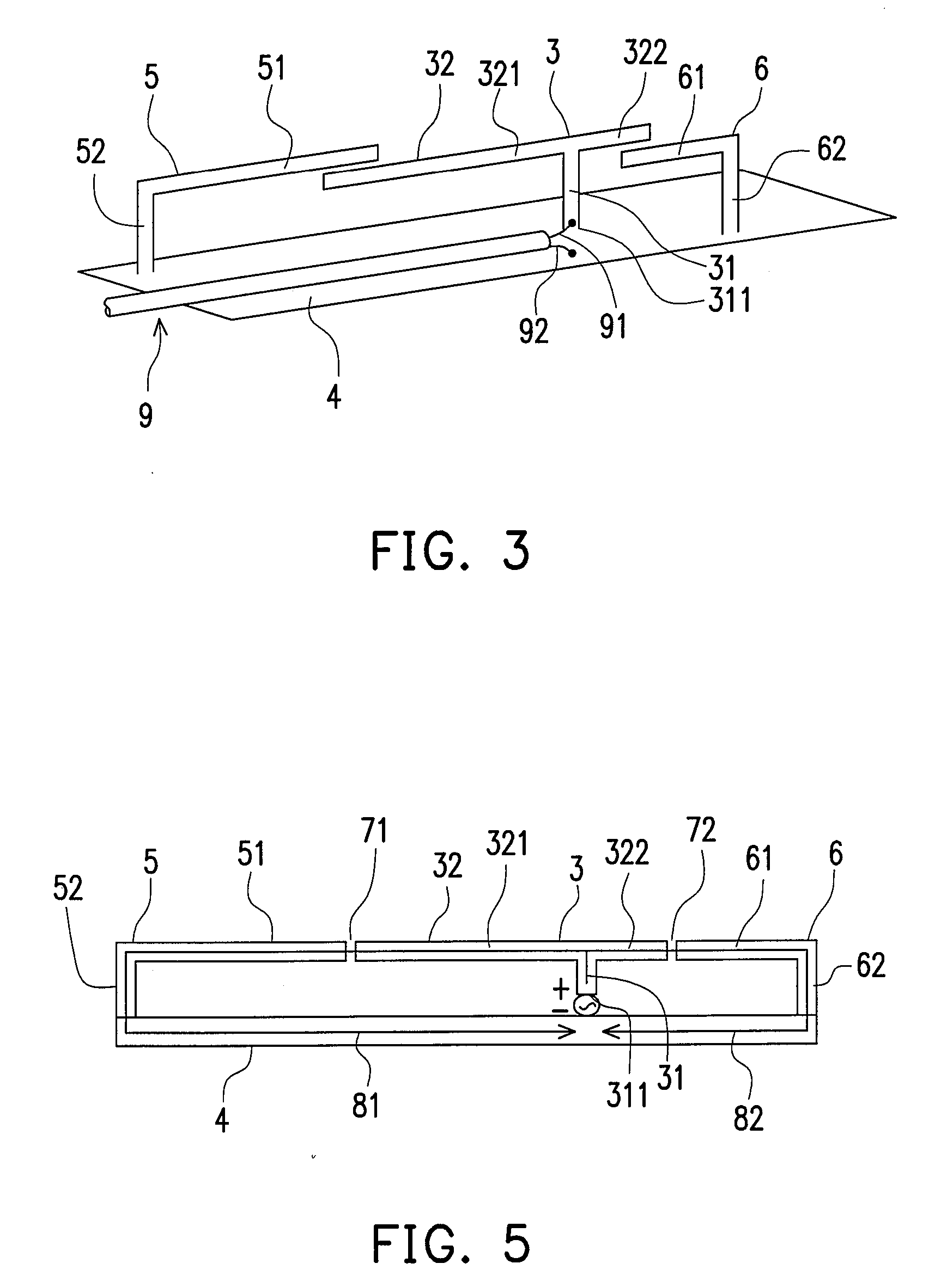
[0031]Referring to FIG. 3, the multi-frequency antenna in the first embodiment of the present invention includes a T-shaped radiator 3, a first L-shaped radiator 5 and a second L-shaped radiator 6, a ground plane 4, and a feeder cable 9. In this embodiment, a first arm 321 and a second arm 322 of the T-shaped radiator 3 are suspended above the ground plane 4, but the bottom 311 of a first portion 31 of the T-shaped radiator 3 is connected with a positive signal wire 91 of the feeder cable 9 for transmitting an electrical signal to the T-shaped radiator 3, and the negative signal wire 92 of the feeder cable 9 is electrically connected with the ground plane 4.

[0032]The two L-shaped radiators includes a first L-shaped radiator 5 and a second L-shaped radiator 6 opposite to the first L-shaped radiator 5. The longer portion 51 of the first L-shaped radiator 5 and the longer portion 61 of the second L-shaped radiator 6 point to each other and are spaced away from and parallel to the secon...

Example

[0037]Referring to FIG. 6, the multi-frequency antenna of a second embodiment of the present invention includes a T-shaped radiator 3, a first L-shaped radiator 5 and a second L-shaped radiator 6, a ground plane 4, and a feeder cable 9. The T-shaped radiator 3, the first L-shaped radiator 5, and the second L-shaped radiator 6 are elongated metal element. In this embodiment, a first arm 321 and a second arm 322 of the T-shaped radiator 3 are suspended above the ground plane 4, but the bottom 311 of the first portion 31 of the T-shaped radiator 3 is connected with the positive signal wire 91 of the feeder cable 9 for transmitting an electrical signal to the T-shaped radiator 3, and the negative signal wire 92 of the feeder cable 9 is electrically connected with the ground plane 4.

[0038]The two L-shaped radiators include a first L-shaped radiator 5 and a second L-shaped radiator 6 opposite to the first L-shaped radiator 5. The longer portion 51 of the first L-shaped radiator 5 and the ...

Example

[0039]Referring to FIG. 7, the multi-frequency antenna in a third embodiment of the present invention includes a T-shaped radiator 3, a first L-shaped radiator 5 and a second L-shaped radiator 6, a ground plane 4, and a feeder cable 9. The T-shaped radiator 3, the first L-shaped radiator 5, the second L-shaped radiator 6, and the ground plane 4 are all obtained by punching metal sheets. In this embodiment, a first arm 321 and a second arm 322 of the T-shaped radiator 3 are suspended above the ground plane 4, but the bottom 311 of the first portion 31 of the T-shaped radiator 3 is connected with the positive signal wire 91 of the feeder cable 9 for transmitting an electrical signal to the T-shaped radiator 3, and the negative signal wire 92 of the feeder cable 9 is electrically connected with the ground plane 4.

[0040]The two L-shaped radiators include a first L-shaped radiator 5 and a second L-shaped radiator 6 opposite to the first L-shaped radiator 5. The longer portion 51 of the f...


PUM


Abstract

A multi-frequency antenna with dual loops is provided. The antenna includes a T-shaped radiator having a first arm and a second arm of unequal lengths as a main body, and two grounded L-shaped radiators, so as to form dual loops. Thus, the antenna can operate in a high-frequency operation mode and a low-frequency operation mode. With the dual loops, the antenna obtains enough bandwidths at high frequency, and also meets the requirements of low frequency. More specific, the antenna meets the requirements of high-frequency systems, such as DCS/PCS/UMTS and those of low-frequency systems, such as AMPS/GSM.

Description

CROSS-REFERENCE TO RELATED APPLICATION[0001]This application claims the priority benefit of Taiwan application serial no. 95120597, filed Jun. 9, 2006. All disclosure of the Taiwan application is incorporated herein by reference.BACKGROUND OF THE INVENTION[0002]1. Field of the Invention[0003]The present invention relates to a multi-frequency antenna with dual loops. More particularly, the present invention relates to a multi-frequency antenna which can operate in two different frequency bands with the dual loops thereof.[0004]2. Description of Related Art[0005]The personal mobile communications technology has already proven its huge potential and business opportunity in the wireless communications industry. In the course of advancement, various systems adopting different technologies and frequency bands have been developed and used in different areas and markets. However, this also brings troubles and inconvenience to system suppliers and consumers due to different systems, such as ...

Claims


Application Information

Patent Timeline
IPC IPC(8): H01Q1/24H01Q5/15
CPCH01Q1/38H01Q5/371H01Q21/29H01Q7/00
Inventor CHUNG, MING-HSUNCHIU, TSUNG-WENHSIAO, FU-RENLIN, YU-CHINGLAN, CHUN-CHING
Owner ADVANCED CONNECTEK INC
Why Eureka
Try Eureka