Image quality analysis with test pattern

Active Publication Date: 2007-12-13
SICK AG
View PDF33 Cites 67 Cited by
  • Summary
  • Abstract
  • Description
  • Claims
  • Application Information

AI Technical Summary

Benefits of technology

[0008] It is therefore an object of this invention to provide a system for and a method of image quality analysis which is more consistent.
[0011] The subject invention results from the realization that more consistent, less subjective image quality analysis for use by operators having varying skills can be achieved by automating the image quality analysis, such that an operator need not perform a series of subjective steps including choices and / or data inputs in order for desired values reflecting image quality to be determined.
[0012] The present invention provides an automated method and system for analysis of image quality, such as for an image obtained by a camera in a camera tunnel system. The invention includes providing a test pattern for application to a package for placement in the camera tunnel system, capturing an image of the package using the camera tunnel system, wherein the image includes an image of the test pattern, and identifying the image of the test pattern. In various embodiments, the present invention also includes analyzing the image of the test pattern, in one example for generating one or more image quality metrics, and / or comparing the one or more metrics with a threshold value to form a comparison, and / or determining the performance of the camera in the camera tunnel system using the comparison. In another embodiment, the present invention automatically adjusts the image quality, including settings of the camera, so as to bring the camera's performance to within a desired range which may be defined by a threshold value, thus improving the overall performance of a camera tunnel system.

Problems solved by technology

Such an operator-based influence adversely impacts the consistency of the measurement of such metrics over time and across various systems.
This inspection requires a skilled operator and does not ensure consistency, especially across various systems, because in each case the particular operator follows a series of steps or prompts, each of which is subjective and subject to variations among different operators and systems.
The subjective nature of using the operator to evaluate an image fails to meet the need for a consistent, repeatable and verifiable evaluation of the system.
Additionally, even if an entire cadre of skilled and consistent operators were available, the need for a skilled operator limits the value of such an operator-based system.
Consequently, current manual image analysis techniques do not offer a consistent, repeatable, objective and verifiable measure of the camera system's performance.

Method used


Image

  • Image quality analysis with test pattern
  • Image quality analysis with test pattern
  • Image quality analysis with test pattern

Examples


Embodiment Construction

[0052] Aside from the preferred embodiment or embodiments disclosed below, this invention is capable of other embodiments and of being practiced or being carried out in various ways. Thus, it is to be understood that the invention is not limited in its application to the details of construction and the arrangements of components set forth in the following description or illustrated in the drawings. If only one embodiment is described herein, the claims hereof are not to be limited to that embodiment. Moreover, the claims hereof are not to be read restrictively unless there is clear and convincing evidence manifesting a certain exclusion, restriction, or disclaimer.

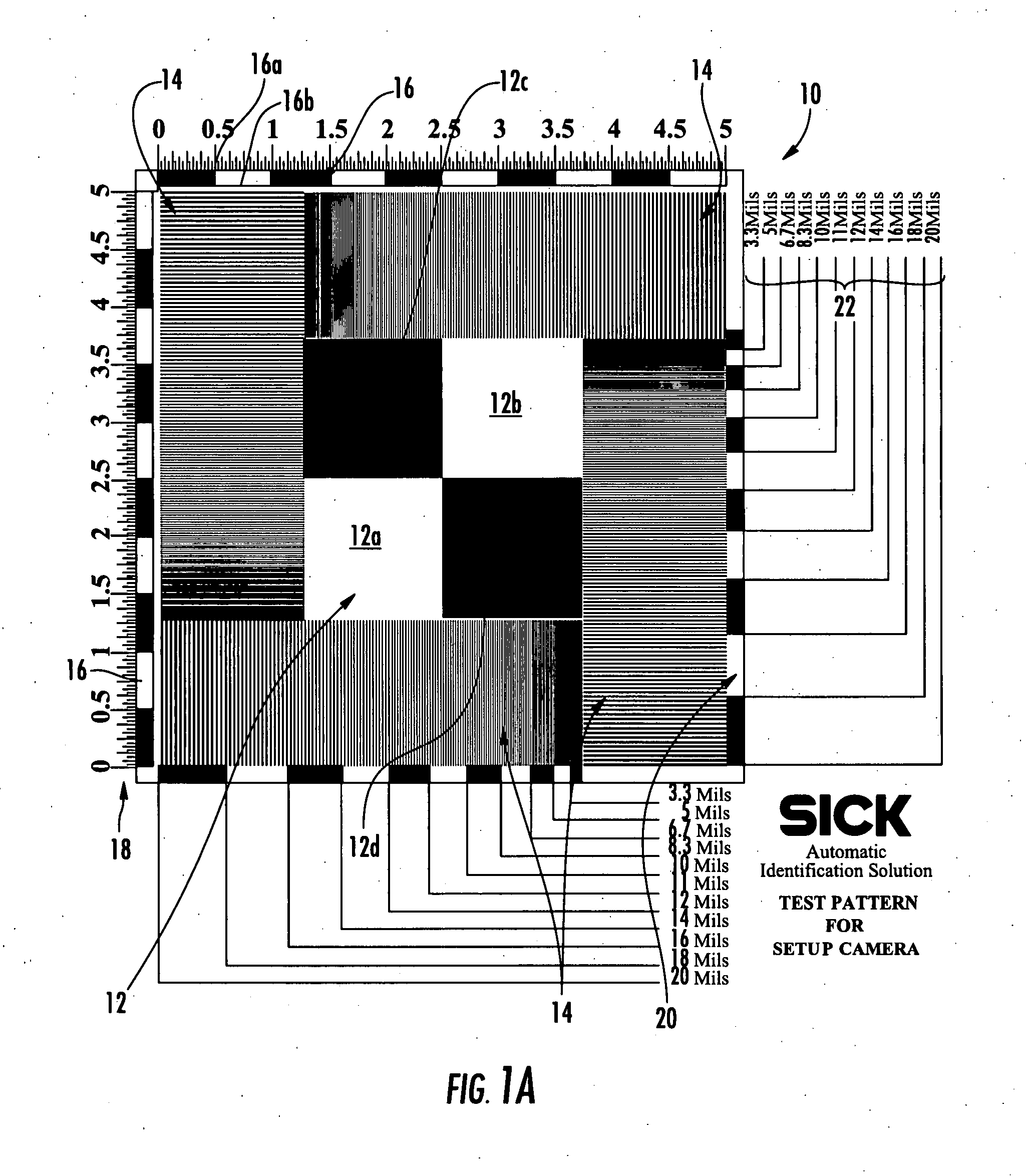
[0053]FIG. 1A shows one example test pattern in accordance with the present invention. As is shown in FIG. 1A, test pattern 10 has various unique and novel features that enable its identification and capture by a high speed camera. Moreover, unique features of test pattern 10 enable the image analysis tool of the present ...


PUM


Abstract

A system for the automated analysis of image quality obtained by a camera in a camera tunnel system includes a test pattern on an item for placement in the camera tunnel system and an imaging subsystem configured to capture an image of the item using the camera tunnel system, wherein the image includes an image of the test pattern. The system further includes an image analysis tool configured to automatically identify and analyze the image of the test pattern for generating one or more image quality metrics.

Description

RELATED APPLICATIONS [0001] This application claims the benefit of and priority to U.S. Provisional Patent Application Ser. No. 60 / 794,007 filed Apr. 21, 2006, which is incorporated herein by reference.FIELD OF THE INVENTION [0002] This subject invention relates to image quality analysis, and in one example, automated analysis of image quality utilizing a test pattern for use in a camera tunnel system. BACKGROUND OF THE INVENTION [0003] Multiple camera tunnel systems can offer very high read rates when they are properly configured and maintained. In order to ensure that such camera tunnel systems are properly functioning, the performance of the camera in such systems needs be measured and compared to some standard. Currently such camera quality measurements are conducted by human operators and as such they are very dependent on variance from one operator to the next. The measurement metrics for the performance quality of the camera in such tunnel systems tends to include a very larg...

Claims


Application Information

Patent Timeline
IPC IPC(8): H04N9/093
CPCG06T7/001
Inventor DWINELL, JOHNBIAN, LONG XIANG
Owner SICK AG
Why Eureka
Try Eureka