Arrangement for and method of projecting an image with safety circuitry

Active Publication Date: 2007-12-13
MICROVISION
View PDF20 Cites 25 Cited by
  • Summary
  • Abstract
  • Description
  • Claims
  • Application Information

AI Technical Summary

Benefits of technology

[0012]An additional object is to provide a miniature, compact, lightweight, and portable color image projection module useful in many instruments of different form factors.
[0013]In keeping with these objects and others, which will become apparent hereinafter, one feature of this invention resides, briefly stated, in an image projection arrangement for, and a method of, projecting a two-dimensional image, especially of high brightness and in color. The arrangement inc

Problems solved by technology

If the monitor photodiode were to fail, or to become electrically disconnected from the feedback circuit, then the feedback signal would be lost, and the feedback circuit would increase the laser output power, possibly to a level exceeding regulatory limits and compromi

Method used


Image

  • Arrangement for and method of projecting an image with safety circuitry
  • Arrangement for and method of projecting an image with safety circuitry
  • Arrangement for and method of projecting an image with safety circuitry

Examples


Embodiment Construction

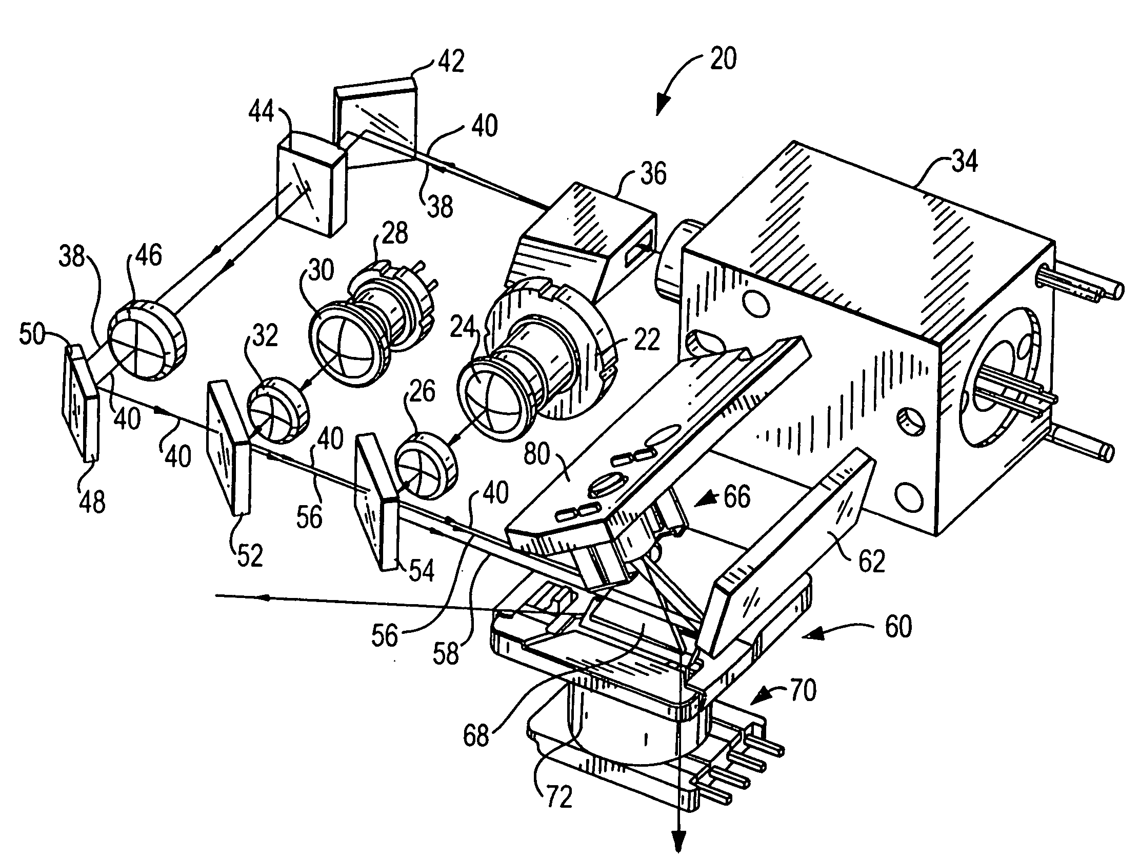
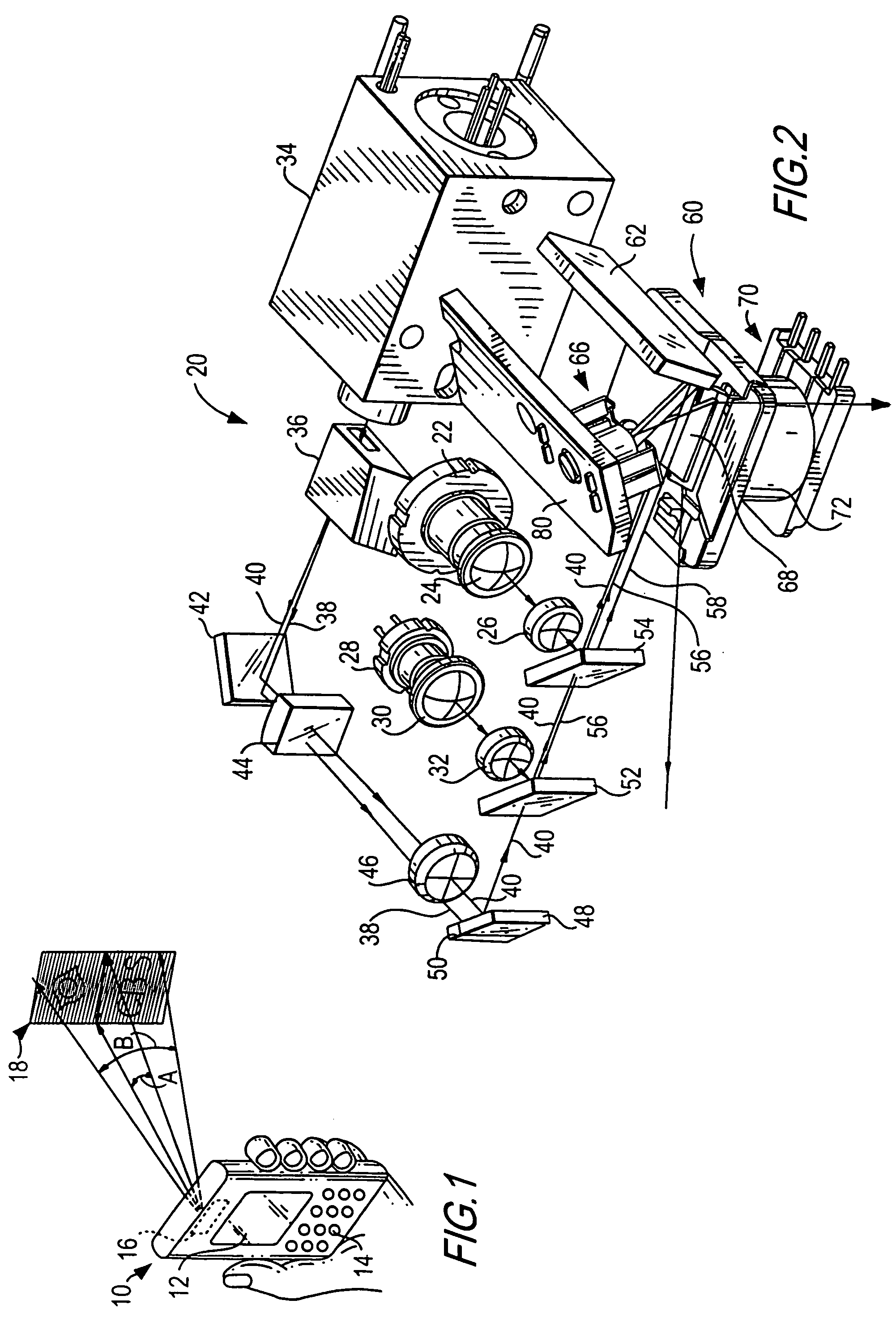
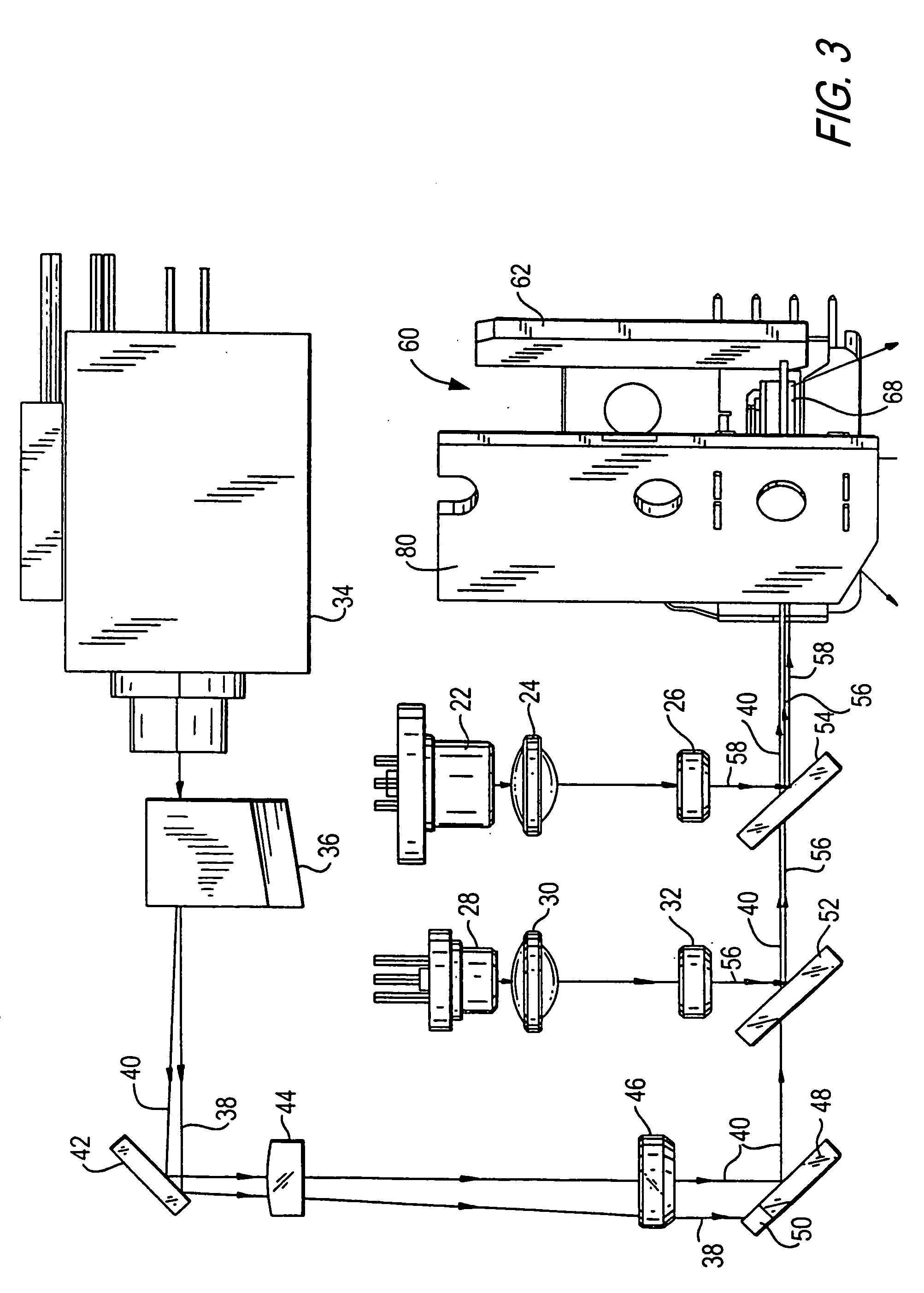
[0033]Reference numeral 10 in FIG. 1 generally identifies a hand-held instrument, for example, a personal digital assistant, in which a light weight, compact, image projection arrangement 20, as shown in FIG. 2, is mounted and operative for projecting a two-dimensional color image on a projection surface at a variable distance from the instrument. By way of example, an image 18 is situated within a working range of distances relative to the instrument 10.

[0034]As shown in FIG. 1, the image 18 extends over an optical horizontal scan angle A extending along the horizontal direction, and over an optical vertical scan angle B extending along the vertical direction, of the image. As described below, the image is comprised of illuminated and non-illuminated pixels on a raster pattern of scan lines swept by a scanner in the arrangement 20.

[0035]The parallelepiped shape of the instrument 10 represents just one form factor of a housing in which the arrangement 20 may be implemented. The inst...


PUM


Abstract

Red, blue and green lasers respectively emit a plurality of red, blue and green laser beams having respective output powers. The beams are optically focused and collinearly arranged to form a composite beam which is swept by a pair of scan mirrors in a pattern of scan lines on a projection surface, each scan line having a number of pixels. A controller causes selected pixels to be illuminated, and rendered visible, by the composite beam to produce an image. A safety circuit detects a malfunction of at least one of the lasers and the scan mirrors, and deenergizes the at least one of the lasers and the scan mirrors upon detection of the malfunction.

Description

BACKGROUND OF THE INVENTION[0001]1. Field of the Invention[0002]The present invention generally relates to projecting a two-dimensional image of high quality, especially in color, using high power lasers and scan mirror drives, without exceeding governmental regulatory exposure limits on laser power, thereby enhancing viewer and bystander safety during image projection.[0003]2. Description of the Related Art[0004]It is generally known to project a two-dimensional image on a projection surface based on a pair of scan mirrors which oscillate by respective mirror drives over scan angles in mutually orthogonal directions to scan a laser beam over a raster pattern comprised of a plurality of scan lines. The image is created in the raster pattern by modulating a laser on and off at selected times, thereby illuminating selected pixels and not illuminating other pixels in each scan line. Color images can be obtained by modulating red, blue and green lasers and illuminating the selected pixe...

Claims


Application Information

Patent Timeline
IPC IPC(8): G03B21/20G02B26/08
CPCG02B26/101G02B27/0031H04N9/3173H04N9/3129G03B21/14G03B21/2033G03B21/2066G03B21/2086
Inventor YAVID, DMITRIYSTERN, MIKLOSMAZZ, THOMASDIFAZIO, COSTANZOTAN, CHINHWITTENBERG, CARLGONZALEZ, DANIEL
Owner MICROVISION
Why Eureka
Try Eureka