Network system and server

a network system and server technology, applied in the field of network system and server, can solve the problems of high cost, difficult determination of location with high accuracy, application only to equipment using wireless lans, etc., and achieve the effect of accurately determining the range of a location

Inactive Publication Date: 2007-12-13
HITACHI LTD
View PDF7 Cites 47 Cited by
  • Summary
  • Abstract
  • Description
  • Claims
  • Application Information

AI Technical Summary

Benefits of technology

[0013]Accordingly, also in a wired LAN, the location of equipment or the location of a user can be determined, and because other than an essentially required LAN switch, only one PC is used, the location can be determined at low cost, and by limiting the wiring range from the LA

Problems solved by technology

The conventional technique concerning the method for obtaining a location in a building described in JP-A-2005-110314 has firstly a problem that it can be applied only to equipment using a wireless LAN.
Secondly, only one wireless LAN access point is required when not carrying out the location measurement, while a plurality of wireless LAN access points and the equipment for the measurement are required in order to apply this method, thus presenting a problem of high cost.
Thirdly, it has a problem that the determination of a location with high accuracy is difficult in the state of the art today.
Moreover, the conventional technique concerning determining and retrieving the installation place of a LAN component unit described in JP-A-2003-32257 has

Method used


Image

  • Network system and server
  • Network system and server
  • Network system and server

Examples


embodiment 1

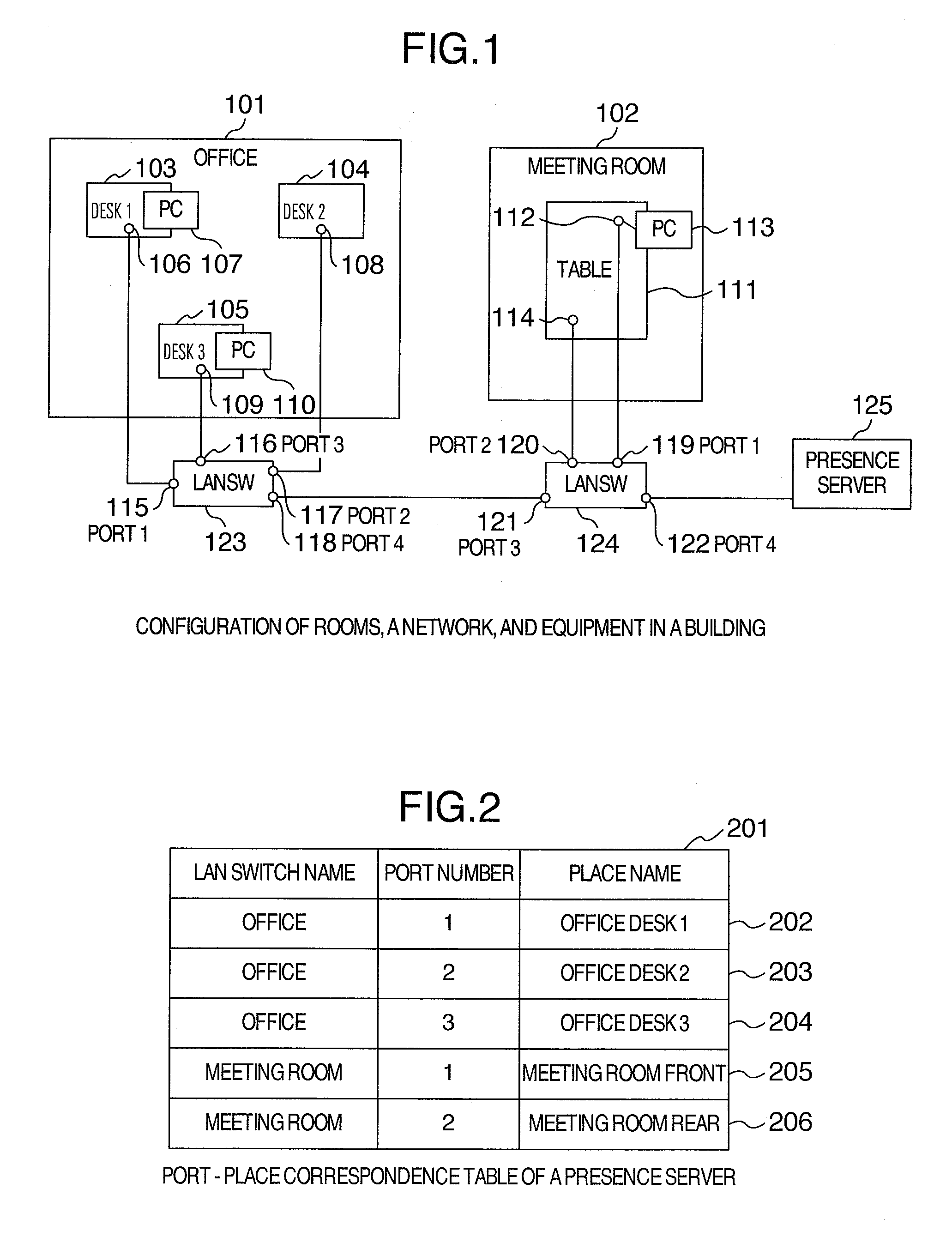
[0036]A first embodiment of the present invention is described. In this embodiment, only wired LAN equipment via Ethernet (registered trademark) (IEEE 802.2) is used. The configuration of rooms, a network, and equipment in a building according to this embodiment is described using FIG. 1. In this embodiment, an office 101 and a meeting room 102 exist in a building. However, the office 101 and the meeting room 102 may exist in different buildings. Moreover, the Ethernet connecting between the office 101 and the meeting room 102 may be a wide area network.

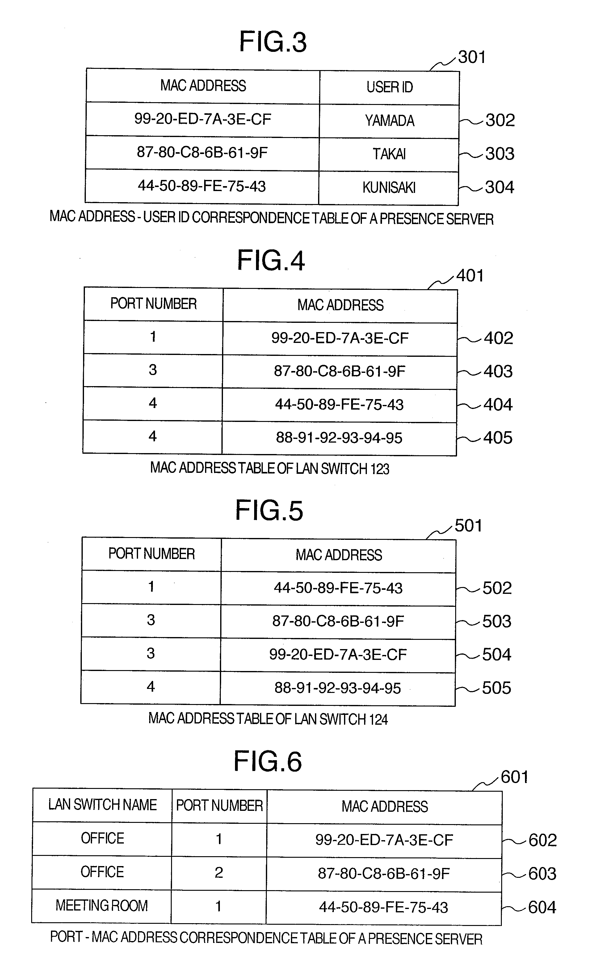
[0037]The office 101 is a free address (hotelling) office, and a worker is assigned a desk when he / she comes to the office every day. In the office 101, a desk 1 103, a desk 2 104, and a desk 3 105 exist, and other than these a lot of desks also exist. A LAN switch 123 is used in a LAN wired to the office 101, and a LAN switch 124 is used in a LAN wired to the meeting room 102. The LAN switches 123 and 124 have the function to access...

embodiment 2

[0060]Next, a second embodiment of the present invention is described. In this embodiment, wired LAN equipment via VLAN (Virtual LAN) based on IEEE Standard IEEE 802.1Q is used. The configuration of rooms, a network, and equipment in a building in this embodiment is also as shown FIG. 1. Namely, also in this embodiment, the office 101 and the meeting room 102 exist in a building. A difference from the first embodiment is in that VLAN is used in the LAN switches 123 and 124. In other words, the LAN switches 123 and 124 have the function of VLAN and also have the function to access the contents of the MAC address table, which the LAN switch contains, from the outside. Since the VLAN switches 123 and 124 have the VLAN function, in the MAC address table not only the MAC address and the port number but VLAN ID are stored together, as in a typical VLAN switch.

[0061]A different VLAN ID is assigned to each port of the VLAN switch 123. Namely, as the VLAN ID, 1 is assigned for the port 1 115...

embodiment 3

[0076]First, a third embodiment is described. In this embodiment, the presence information is pushed from a LAN switch to the presence server 125. In the embodiment, only the procedure of obtaining the contents of the MAC address table from a LAN switch and merging the above contents in the first embodiment differs. A location information acquisition procedure in this embodiment is described. In this embodiment, a setting of SNMP (Simple Network Management Protocol) linkup trap and linkdown trap to the presence server 125 is established in the LAN switch 123 and LAN switch 124. In other words, the setting is made so that the LAN switch 123 and LAN switch 124 transmit an SNMP trap packet to the presence server 125 when a link between the LAN switch 123, the LAN switch 124 and a network interface of other equipment is established and when a link between the LAN switch 123, the LAN switch 124, and a network interface of other equipment is released.

[0077]When a network interface is conn...


PUM


Abstract

One or more LAN switches capable of accessing the contents of a MAC address table, which the LAN switch contains, from the outside; and a presence server storing in a storage device a first correspondence table between a MAC address of a network interface, which equipment contains, and its user, and a second correspondence table between a port of the above-described LAN switch, and a physical range wired therefrom, are used to thereby obtain a correspondence table between the equipment, its user, and its physical location (range), whereby making applicable also to a wired LAN at the time of determining the location of the equipment or the location of a user using the equipment in a building, and making realizable at low cost, and allowing the location to be determined accurately within a predetermined segmented area, and not being affected even if an IP address is changed.

Description

INCORPORATION BY REFERENCE[0001]The present application claims priority from Japanese application JP2006-161786 filed on Jun. 12, 2006, the content of which is hereby incorporated by reference into this application.BACKGROUND OF THE INVENTION[0002]1. Field of the Invention[0003]The present invention relates to methods for obtaining a location of equipment connected to a network in a building or the like, methods for displaying a list of the equipment, and methods for managing the equipment.[0004]2. Description of the Related Art[0005]Although the methods for obtaining a location of equipment outside a building include the one using GPS, the one using a magnetic sensor, and the like, these methods do not indicate an accurate location in a building. The conventional techniques concerning the methods for obtaining a location in a building include Integrated Wireless LAN Access System (1): Study on Location System, by Ogino, Tsunehara, et al., B-5-203, Proceedings of Institute of Electr...

Claims


Application Information

Patent Timeline
IPC IPC(8): H04L12/28
CPCH04L41/0213H04L41/12H04L67/18H04Q11/0478H04L41/22H04L67/52
Inventor KANADA, YASUSIKODAKA, HIROSHI
Owner HITACHI LTD
Why Eureka
Try Eureka