

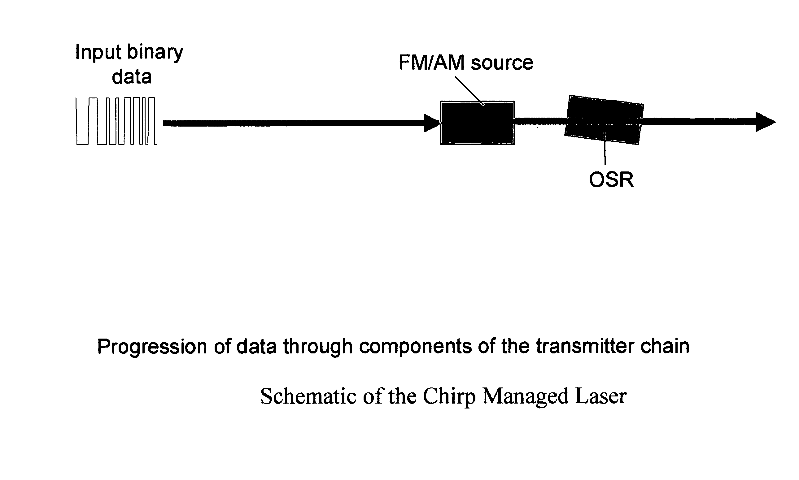
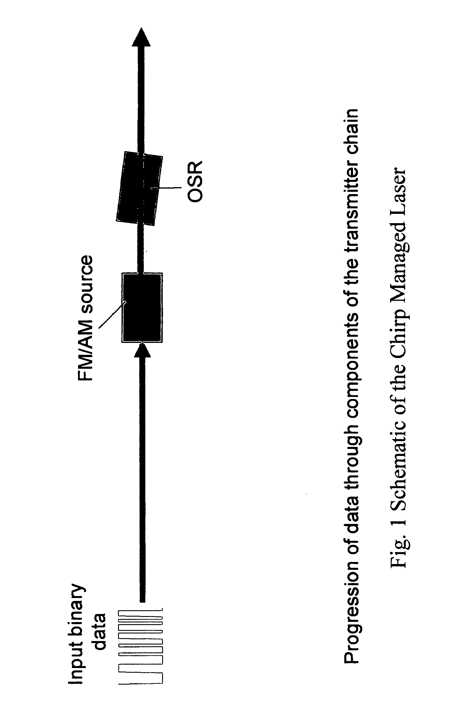
Optical FM source based on intra-cavity phase and amplitude modulation in lasers
a laser and optical fm technology, applied in the field of semiconductor laser diodes, can solve the problems of pattern dependence, low fm generation efficiency, slow time scale from lasing frequency to red shift to lower frequencies, etc., to reduce or eliminate thermal chirp within the laser, increase the fm efficiency of the system, and increase the adiabatic chirp
- Summary
- Abstract
- Description
- Claims
- Application Information
AI Technical Summary
Benefits of technology
Problems solved by technology
Method used
Image

Examples
Embodiment Construction
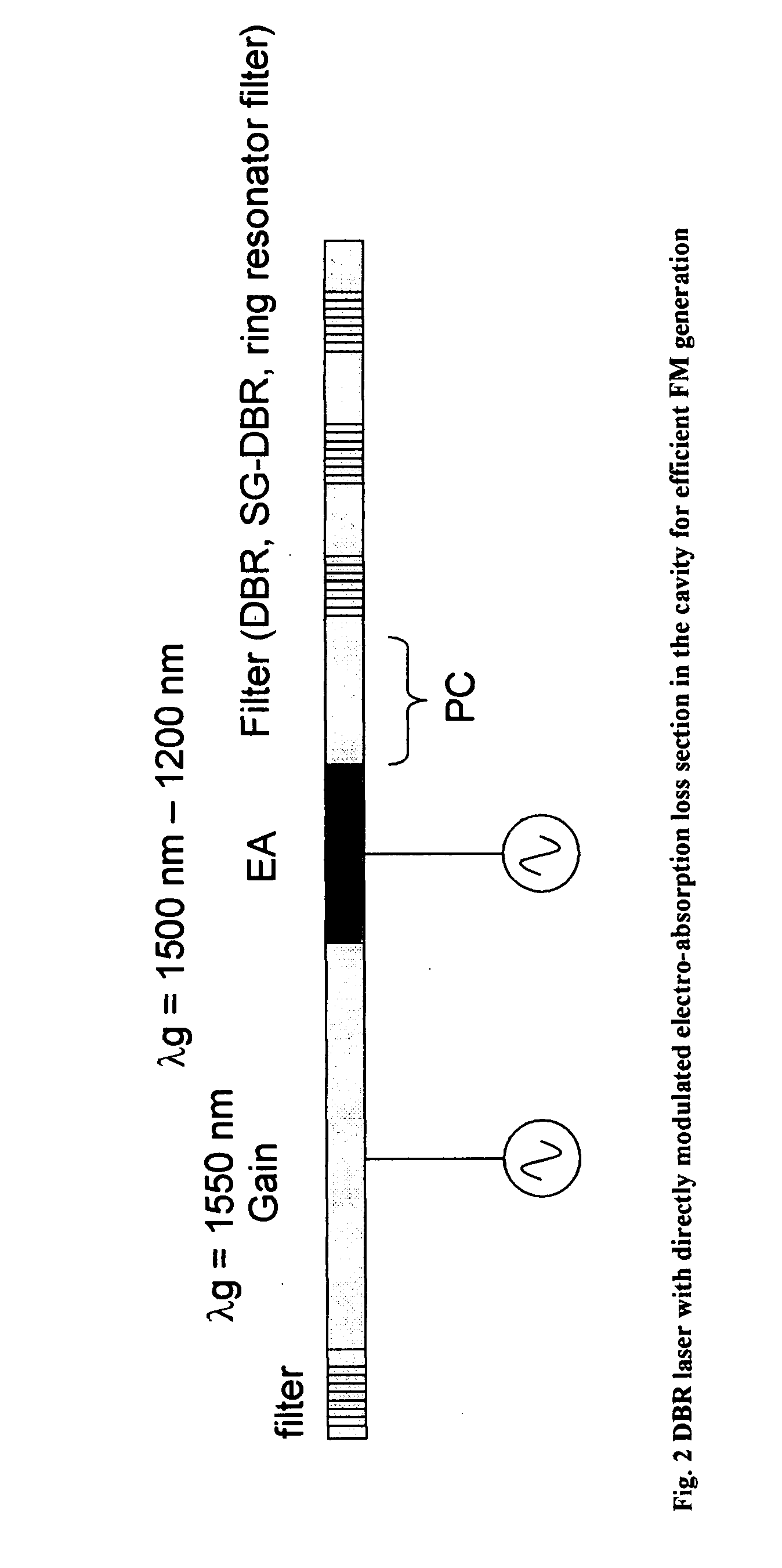
[0044]FIG. 2 shows one preferred embodiment of the present invention, wherein an electro-absorption (EA) modulator is integrated inside a distributed Bragg reflector (DBR) laser cavity. The EA section is reverse biased. Application of a reverse bias voltage to the EA increases cavity loss, which increases the threshold gain for lasing. This increases the threshold carrier density, which causes the laser frequency to shift towards the blue, i.e., so as to provide frequency modulation.
[0045] The large FM efficiency by loss modulation can be understood by considering FIG. 3, which shows the lasing wavelength as a function of injection current into a constant wave (CW) laser. It is known that the lasing wavelength of a CW semiconductor laser depends on the threshold current. Wavelength shifts to the blue as more carriers are injected into the laser below threshold. For example, the wavelength of the laser shifts by 0.2 nm (24 GHz) when the threshold current increases from 7 mA to 9 mA....
PUM
 Abstract
Description
Claims
Application Information