
Power consumption decrease memory management method

a memory management and power consumption technology, applied in the field of memory management methods, can solve the problems of ineffectiveness, difficult to realize effective low power control only at hardware without cooperating with basic system software, and difficult to reduce the power consumption of memory until today, so as to reduce the power consumed by memory largely and reliably.

Inactive Publication Date: 2007-12-13
HITACHI LTD
View PDF6 Cites 40 Cited by
  • Summary
  • Abstract
  • Description
  • Claims
  • Application Information

AI Technical Summary

Benefits of technology

[0020] In the technique disclosed in U.S. Pat. No. 6,215,714, on the other hand, the power consumed by memory devices can be suppressed by executing a refresh to the memory currently in use, to maintain only the data in the memory. But as described above, if the physical memory usage area becomes fragmented across memory devices, the memory device cannot be changed over to a low power mode, thus the reliability of low memory power consumption control is low.
[0022] According to this embodiment of this invention, in a computer system comprising a main storage (memory), control can be performed to reliably reduce the power consumed by the memory without affecting the performance whereby the processor accesses the memory, and the power consumed by the memory can be largely reduced.

Problems solved by technology

In the prior art mentioned above, the main target of the low power control in a computer system was the processor, while on the other hand, the power consumption of the memory was hardly controlled until today.
In general, since physical memory resources are directly managed by basic system software (operating system, etc.) , in practice, it is very difficult to realize effective low power control only at hardware without cooperating with basic system software.
Even when there is assistance of software, such as basic system software, in a method where in a method where power supply to the memory device is simply interrupted in case of which the whole memory device is unused, and memory devices with a high usage frequency are allocated by a program, fragmentation occurs where the used physical memory area spans plural memory devices, which is not effective.
In particular, when the memory is managed by the operating system, fragmentation will usually occur.
Moreover, when the power which a memory consumes is changed from a low power mode state to the normal power mode state in which memory write / read are possible, a delay (latency) occurs in accessing the memory from the processor, and the memory access performance of the processor falls.
However, the methods of allocating memory and of releasing memory allocation are not forms of control which attempt to reduce the power consumption of the memory itself.
For this reason, if the computer system continues running and the memory is managed by the operating system, the area where the physical memory is used usually becomes fragmented, and this method may not be possible to deal with this fragmentation.

Method used


Image

  • Power consumption decrease memory management method
  • Power consumption decrease memory management method
  • Power consumption decrease memory management method

Examples


first embodiment

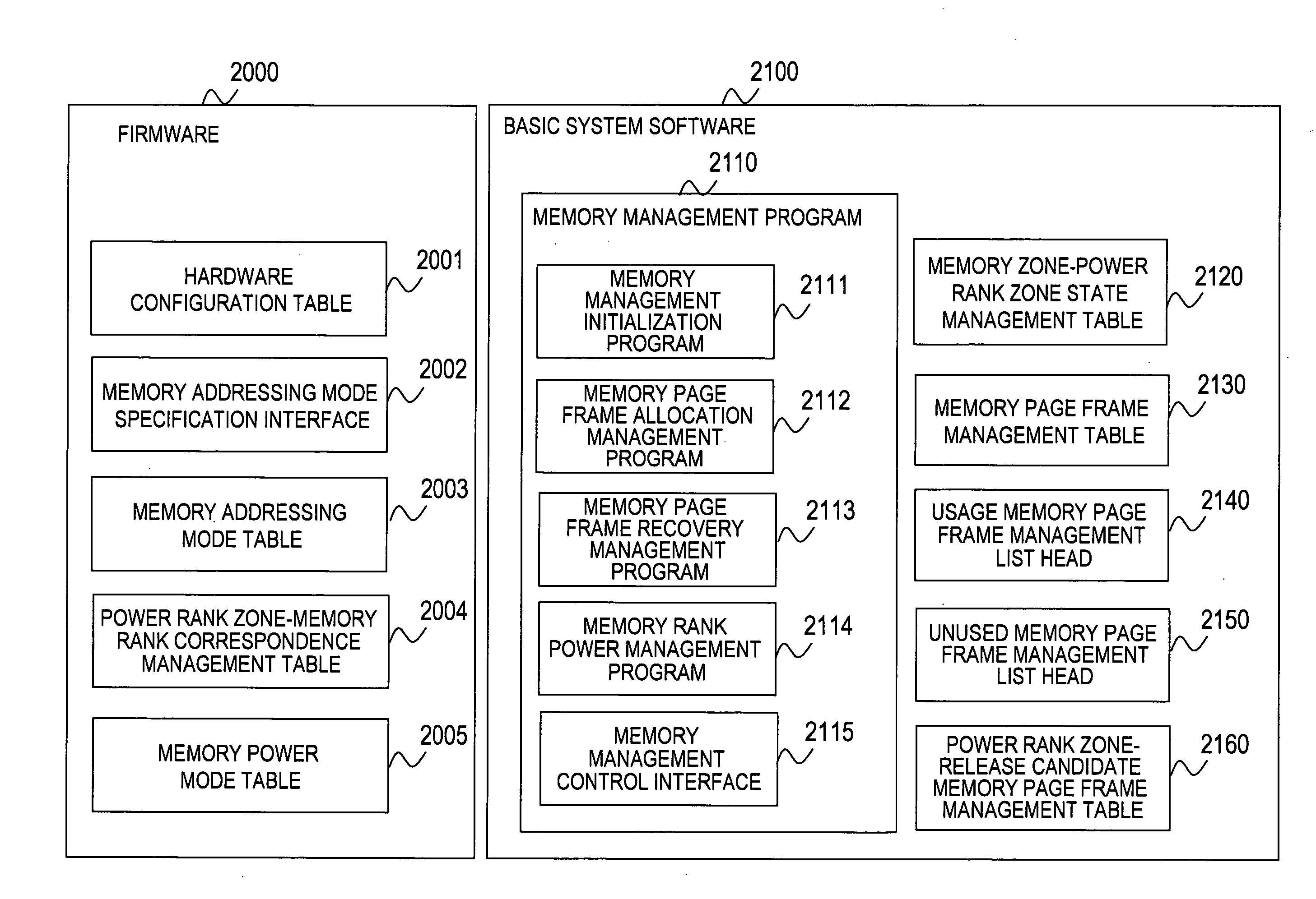
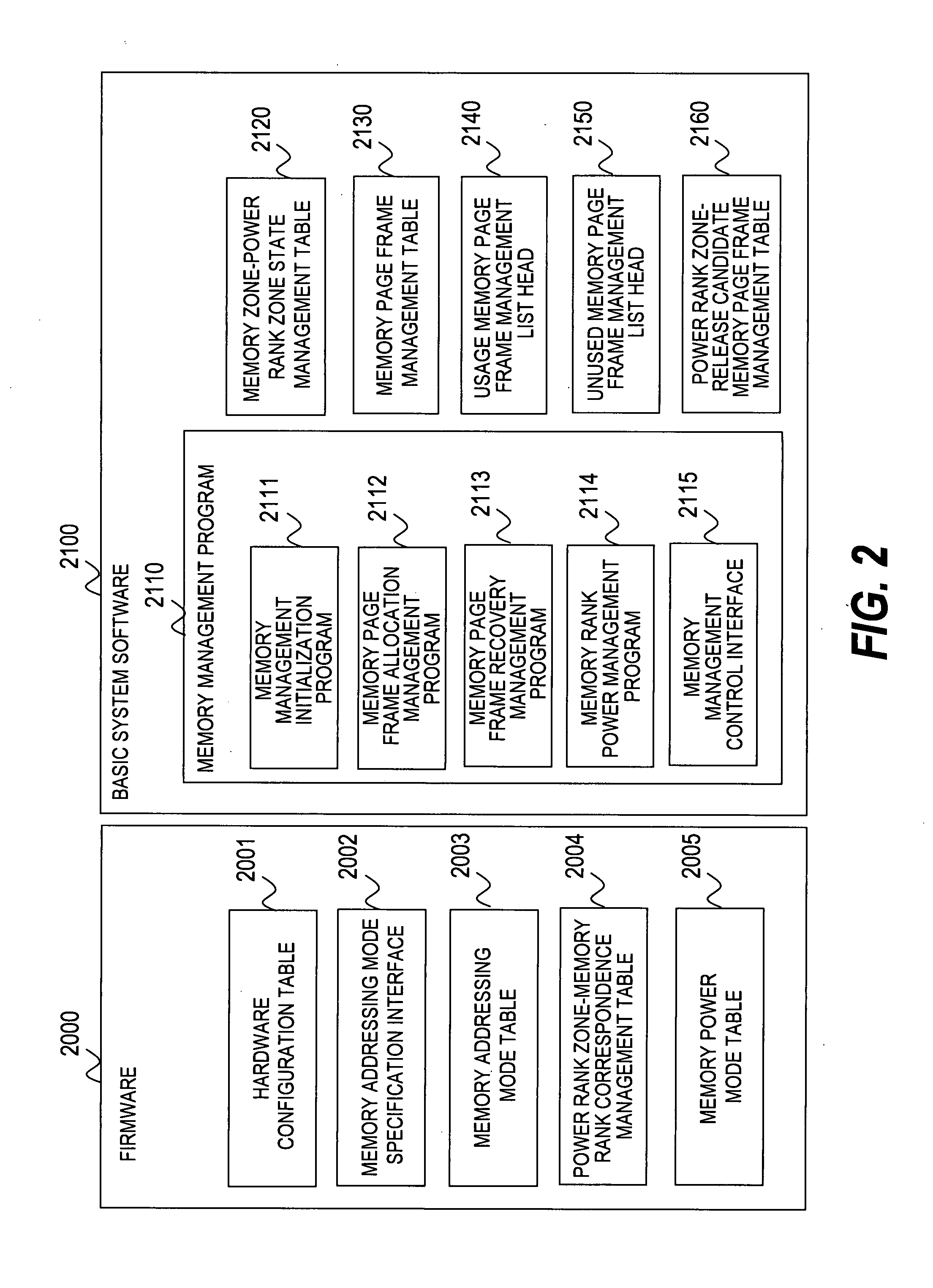
[0046] A first embodiment of the invention will now be described referring to FIG. 1 to FIG. 14.

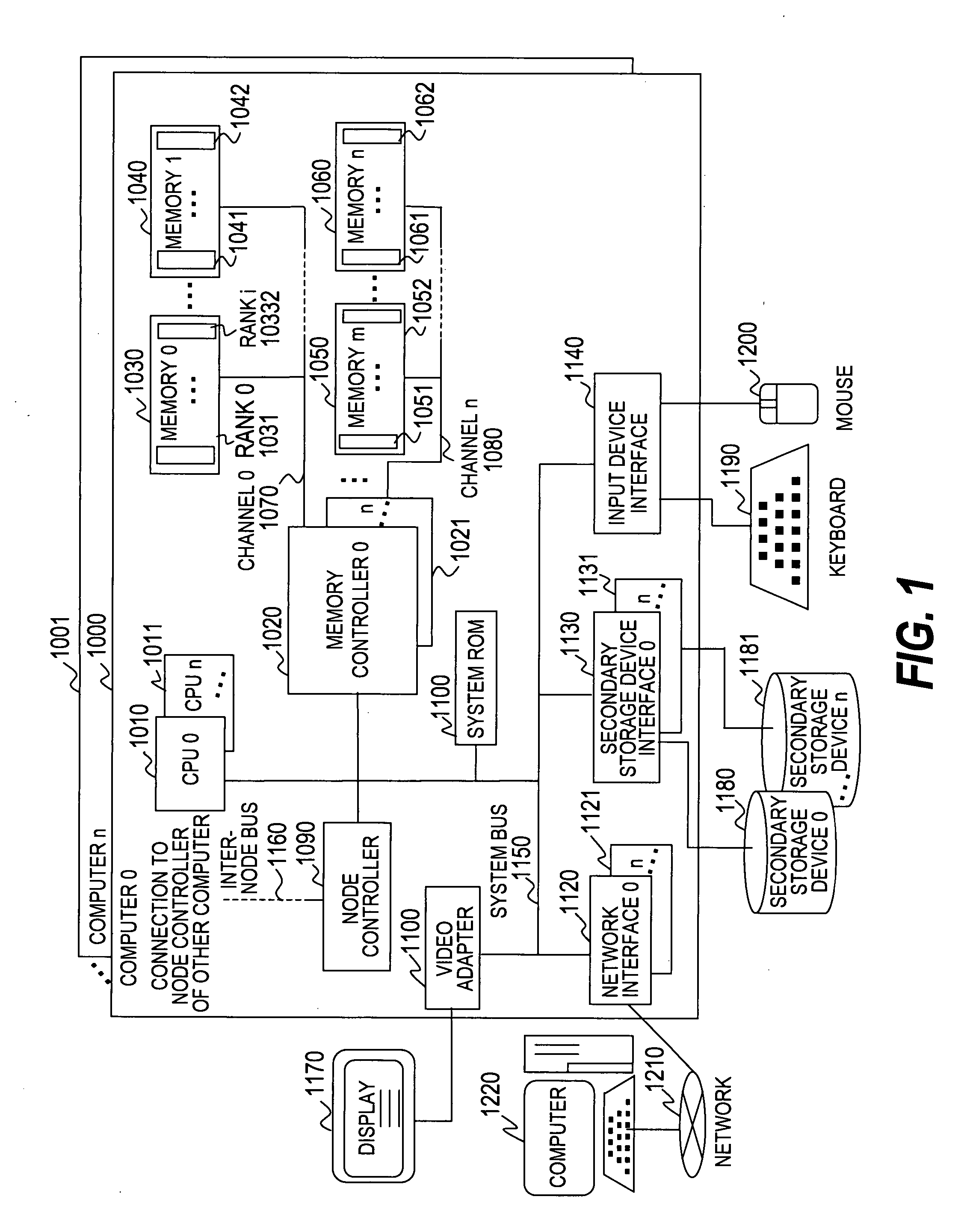
[0047]FIG. 1 is a schematic diagram of a computer system according to the first embodiment of the invention.

[0048] The computer system according to the first embodiment of the invention is provided with computers 1000 to 1001, a keyboard 1190, a mouse 1200, a display 1170, and secondary storages 1180 to 1181. The keyboard 1190, a mouse 1200, a display 1170, and the secondary storages 1180 to 1181 are connected to one or plural computers 1000 to 1001.

[0049] The computer 1000 comprises processors (CPU) 1010 to 1011, a memory controller 1020 to 1021, memories 1030 to 1060, a system ROM 1100, a video adapter 1110, network interfaces 1120 to 1121, secondary storage interfaces 1130 to 1131, and an input device interface 1140.

[0050] The processors (CPU) 1010 to 1011, memory controller 1020 to 1021, memories 1030 to 1060, system ROM 1100, video adapter 1110, network interfaces 1120 to 1121, s...

second embodiment

[0264] A second embodiment of the invention will now be described referring to FIGS. 15 to 17.

[0265] In the second embodiment of the invention, the case of a power consumption memory control different from that of the first embodiment will be described when the computers 1000 to 1001 form a Numa system.

[0266] A Numa system is a system wherein the computer 1000 is connected to another computer 1001 via a node controller 1090 and the internode bus 1160, and the CPUs 1010 to 1011 of each computer 1000 to 1001 can access the memory of each computer 1000 to 1001. In general, the speed with which the CPUs 1010 to 1011 access the memories 1030 to 1060 of the same computer, is faster than the speed with which the CPUs 1010 to 1011 access the memories 1030 to 1060 of another computer.

[0267] In the first embodiment, the memory management program 2110 of the basic system software 2100 manages the memory 1030 to 1060 resources by the zones of the memories 1030 to 1060, and the memory 1030 to...


PUM


Abstract

The power consumed by a memory is reduced without affecting the performance whereby a processor accesses the memory. A state of a power supplied to the memory is controlled to one of an active state wherein a storage area included in the memory rank can be accessed from the processor, and an inactive state wherein access cannot be performed without a delay for each memory rank, the basic system software prevents fragmentation in which the allocated storage area spans a plurality of memory ranks, puts the power state of a memory rank which does not include an allocated storage area into the inactive state, and puts the power state of a memory rank which includes a storage area required for allocation first into the active state.

Description

CLAIM OF PRIORITY [0001] The present application claims priority from Japanese patent application P2006-97586 filed on Mar. 31, 2006, the content of which is hereby incorporated by reference into this application. BACKGROUND OF THE INVENTION [0002] This invention relates to a method of managing the memory of a computer system, and a method of reducing the power consumption of a memory, taking particular account of access performance. [0003] An ordinary computer system is provided with hardware and consumes power due to the operation of the hardware. Specifically, hardware means a processing unit (processor), a main memory unit (memory), a secondary storage, and an Input / Output (I / O) device, etc. [0004] When a computer system consumes a large amount of power, the computer system simultaneously generates a lot of heat. Therefore, a cooling installation from which heat is removed must be installed. Due to the high cost of the power consumed by the computer system and the cooling instal...

Claims


Application Information

Patent Timeline
Patent Type & Authority Applications(United States)
IPC IPC(8): G06F1/32
CPCG06F1/3225
Inventor OGASAWARA, KATSUHISASUGITA, YUMIKO
Owner HITACHI LTD
Learn More