
Process for Repairing Punctured Pneumatic Tire in Tire-Rim Assembly and Repairing System

a technology of pneumatic tires and tire rims, which is applied in vehicle tyre testing, roads, instruments, etc., can solve the problems of affecting the repair effect of pneumatic tires. the effect of reducing the damage of the inner face of the tir

Active Publication Date: 2007-12-20
BRIDGESTONE CORP
View PDF3 Cites 9 Cited by
  • Summary
  • Abstract
  • Description
  • Claims
  • Application Information

AI Technical Summary

Benefits of technology

[0011] The invention targets at a pneumatic tire capable of unavoidably running at a relatively short range under puncture instead of a run-flat tire capable of running over a significant distance (concretely, a running distance of about 200-300 km at a speed of 80 km / h without causing troubles in view of the steering performance) under puncture, and is to provide a process for repairing a punctured pneumatic tire in a tire-rim assembly and a repairing system in which the damage of the tire can be effectively suppressed in the unavoidable running under puncture and the running is restarted by only a simple repairing.
[0028] According to the invention, when using the pneumatic tire capable of unavoidably running at a relatively short range under puncture instead of the run-flat tire capable of running over a significant distance (concretely, a running distance of about 200-300 km at a speed of 80 km / h without causing troubles in view of the steering performance) under puncture, it is possible to provide a process for repairing a punctured pneumatic tire in a tire-rim assembly and a repairing system in which the damage of the tire can be effectively suppressed in the unavoidable running under puncture and the running is restarted by only a simple repairing.

Problems solved by technology

In the puncture of the pneumatic tire, however, the support of load through an internal pressure is lost and also the tire itself has not a reinforcing structure capable of supporting the load, so that the tire is largely deformed at a crushed state and hence the steering performance is apt to be violently lowered, and it is assumed that when the tire is particularly punctured during the running at a high speed, the driver encounters into a very risky status.
Even if the vehicle is unavoidably moved up to the relatively short-range safe place after the puncture, a sidewall portion of the tire is strongly deformed between a rim flange and a road surface in the unavoidable running, and particularly rubber parts inside the sidewall portion of the tire are repeatedly rubbed with each other, so that there is a fear that the inner face of the tire is damaged but also there is a possibility that the outer face of the sidewall portion or further the rim flange or the like are damaged.
In the conventional pneumatic tire, therefore, it is possible to largely damage the tire due to the unavoidable running at the punctured state.
Once the tire is damaged, there is a possibility that the damaged tire can not be turned to an original state even by repairing.
However, there is not yet found a technique of combining the alarm device or the puncture repairing kit with a pneumatic tire having a structure of controlling the damage of the tire produced by the unavoidable running at the punctured state.
However, the side-reinforcing type run-flat tire is mainly developed in order that the running at the run-flat state is enabled by arranging a thick reinforcing rubber on the sidewall portion to increase a bending rigidity of the sidewall portion, so that there is a tendency that when such a tire is generally run at a normal state under an air inflation, the ride comfort and the rim-assembling property are deteriorated as compared with the ordinary pneumatic tire having no reinforcing rubber but also there is a problem that the arrangement of the thick reinforcing rubber brings about the increase of the weight and hence the increase of the rolling resistance.
However, the support should be newly arranged in the tire as an additional member, so that the rim-assembling property is deteriorated by the arrangement of the support as compared with the ordinary pneumatic tire and also there is a problem of increasing the weight and hence the rolling resistance.

Method used


Image

  • Process for Repairing Punctured Pneumatic Tire in Tire-Rim Assembly and Repairing System
  • Process for Repairing Punctured Pneumatic Tire in Tire-Rim Assembly and Repairing System
  • Process for Repairing Punctured Pneumatic Tire in Tire-Rim Assembly and Repairing System

Examples


Embodiment Construction

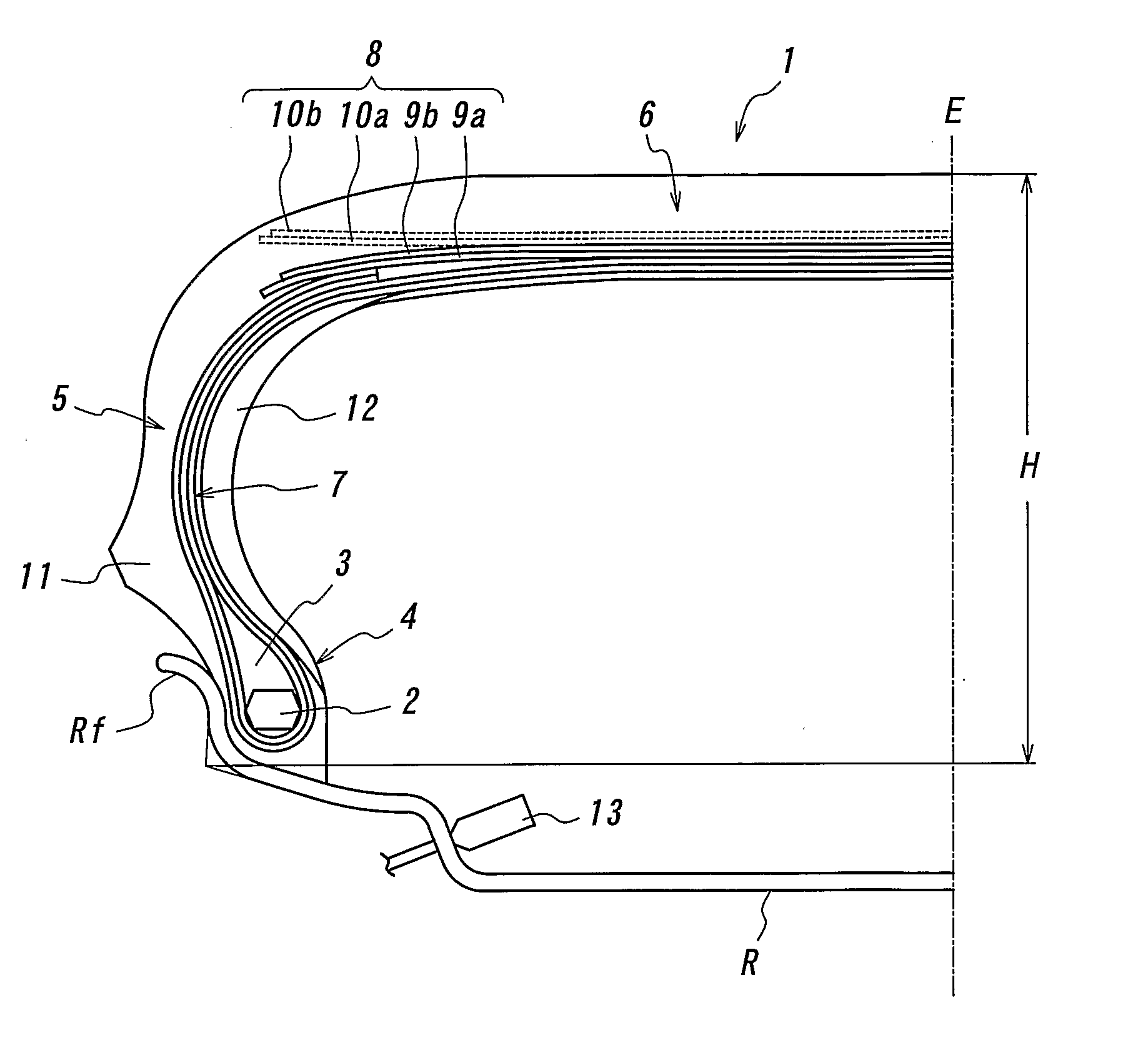
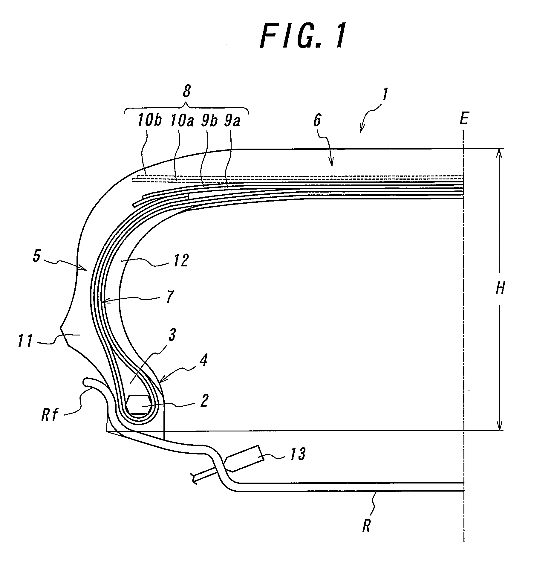
[0032] A pneumatic tire 1 shown in FIG. 1 comprises a pair of bead portions 4 each embedding a bead core 2 and a bead filler 3 located just above the bead core, a pair of sidewall portions 5, a tread portion 6, a carcass 7 of at least one ply, two plies in the illustrated embodiment toroidally extending between the bead portions, and a belt 8 disposed on an outer circumference of a crown portion of the carcass 7 to reinforce the tread portion 6 and comprised of at least one belt layer. The carcass 7 is wound around the bead core 2 from an inside toward an outside in a widthwise direction of the tire, and each turnup end portion thereof is extended to a position of each end portion of the belt 8 to form a so-called envelop structure. In the illustrated embodiment, the belt 8 comprises two main belt layers 9a, 9b, cords of which layers being crossed with each other with respect to an equatorial plane E of the tire, and two auxiliary belt layers 10a, 10b (shown by dotted lines), cords ...


PUM

PropertyMeasurementUnit
speedaaaaaaaaaa
angleaaaaaaaaaa
widthaaaaaaaaaa

Abstract

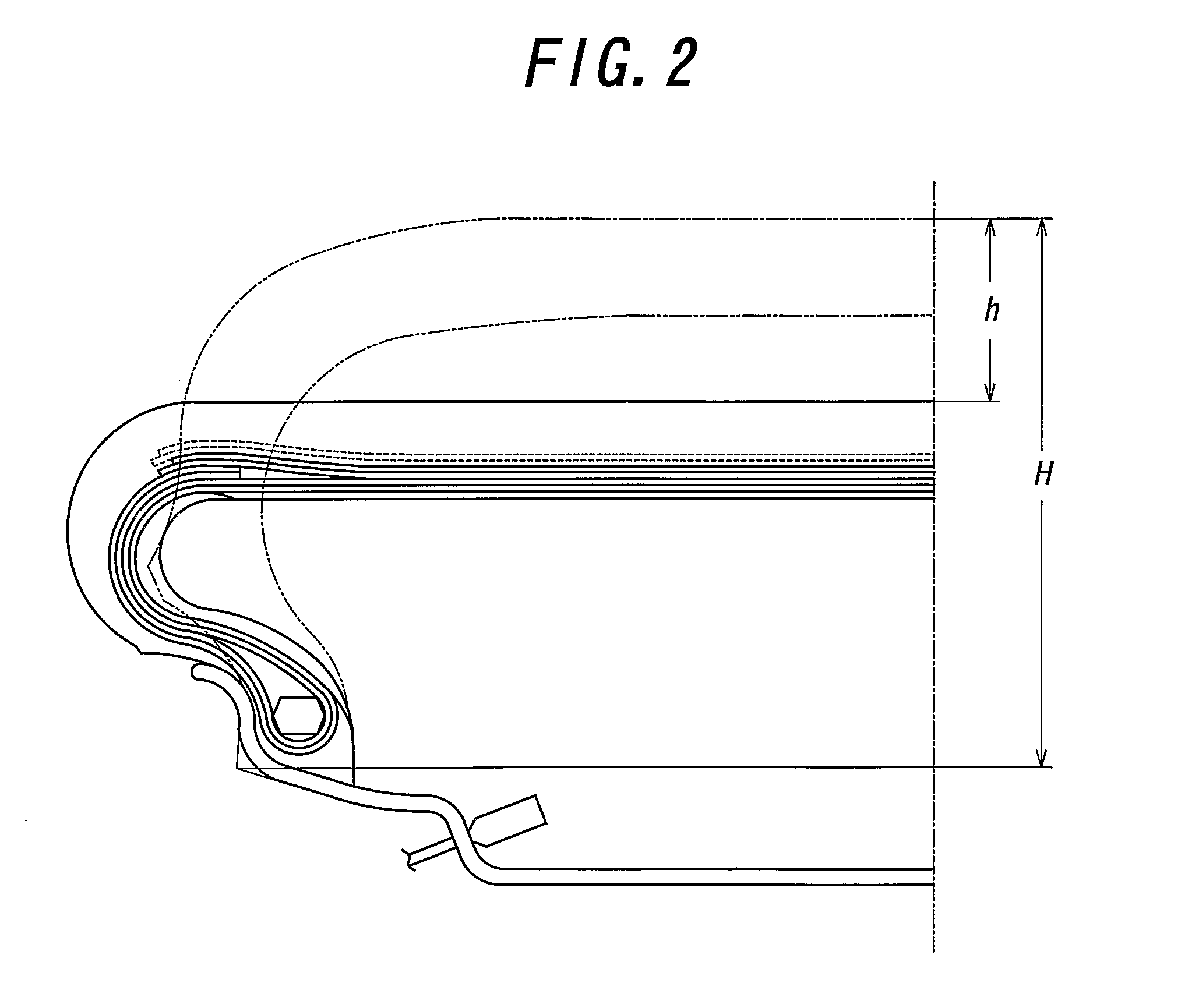
A punctured pneumatic tire in a tire-rim assembly is repaired by mounting on a vehicle the tire-rim assembly provided with an internal pressure alarm means, said tire comprising an auxiliary load-supporting structure satisfying a requirement that an deformation quantity of the tire in a radial direction thereof at a rim-assembled state under a load corresponding to 90% of a maximum load capacity at an internal tire pressure of zero is within a range of 30-60% of a section height of the tire under no load at the internal tire pressure of zero; detecting a puncture of the tire produced during the running of the tire by the internal pressure alarm means; unavoidably running the punctured tire to a relatively short-range safe place to quickly stop the vehicle; and refilling gas to a given internal pressure by a gas filling means equipped on the vehicle while occluding a punctured hole with a puncture repairing means equipped on the vehicle.

Description

TECHNICAL FIELD [0001] This invention relates to a process for repairing a punctured pneumatic tire in a tire-rim assembly and a repairing system. BACKGROUND ART [0002] In general, when the pneumatic tire is punctured during the running, the vehicle is moved (evacuated) at a decelerated rate up to a safe place such as a tire repairing factory or the like, which is located in a relatively short range from the punctured position (concretely, about 50 km at maximum, usually about 10-20 km), and then the punctured tire is subjected to a repairing at this place. [0003] In the puncture of the pneumatic tire, however, the support of load through an internal pressure is lost and also the tire itself has not a reinforcing structure capable of supporting the load, so that the tire is largely deformed at a crushed state and hence the steering performance is apt to be violently lowered, and it is assumed that when the tire is particularly punctured during the running at a high speed, the driver...

Claims


Application Information

Patent Timeline
Patent Type & Authority Applications(United States)
IPC IPC(8): B60C23/04B29C73/16B60C17/00
CPCB29C73/166B60C2019/006B60C17/00B29L2030/00
Inventor WATANABE, SHINICHIKNOTHE, FRANKRUNTSCH, GERDLEISTER, GUENTERKLEMPAU, FRANK
Owner BRIDGESTONE CORP
Learn More