
Orienting Arrangement for Mirror or Light Source

a technology for orienting arrangements and mirrors, applied in the direction of machine supports, instruments, etc., can solve the problems of complex and easy failure of known remotely adjustable outside mirror arrangements for vehicles, and many parts, including relatively fragile gear sections, are required to be incorporated into the mirror housing

Inactive Publication Date: 2007-12-20
FLEXSYS
View PDF3 Cites 20 Cited by
  • Summary
  • Abstract
  • Description
  • Claims
  • Application Information

AI Technical Summary

Benefits of technology

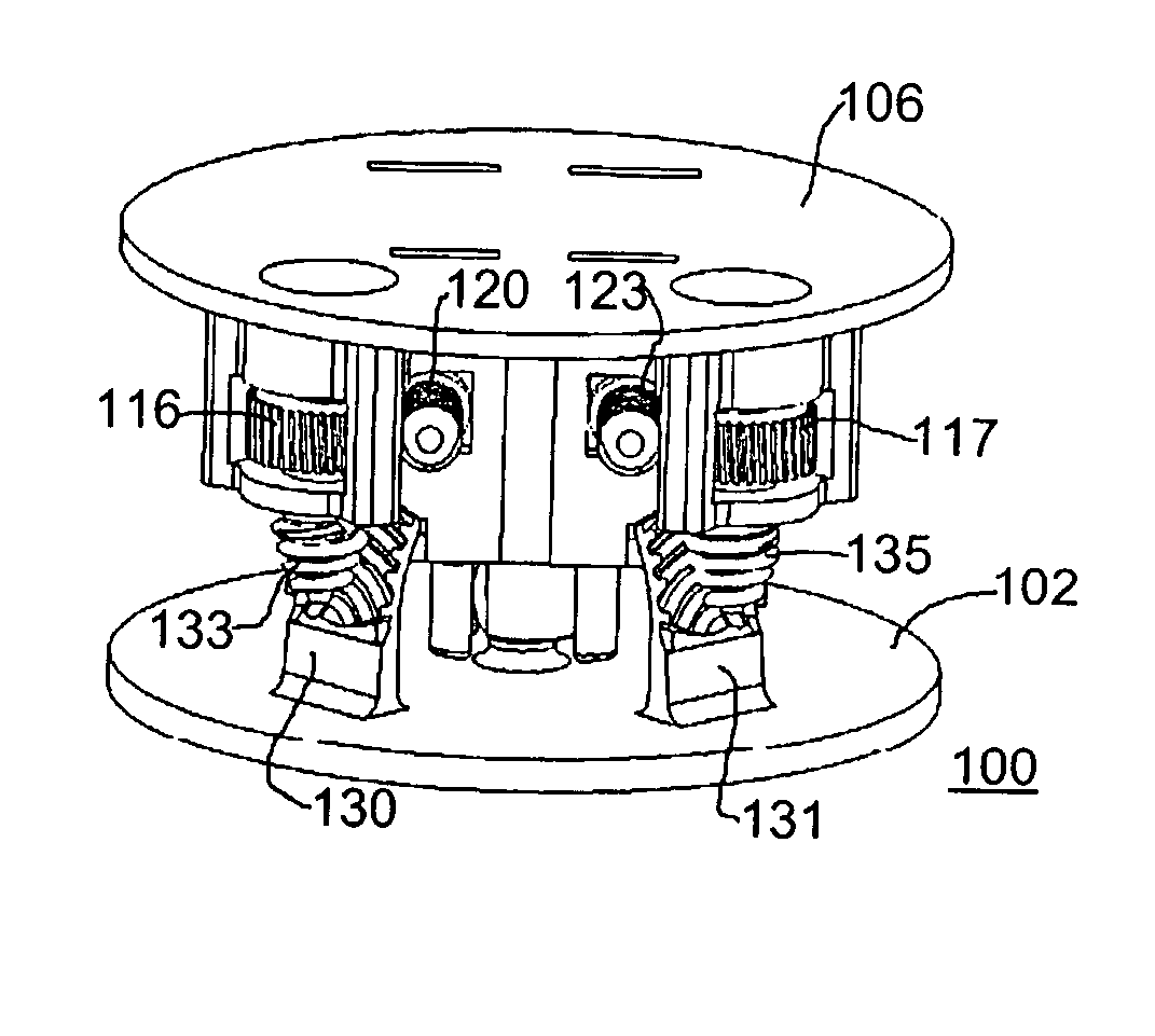
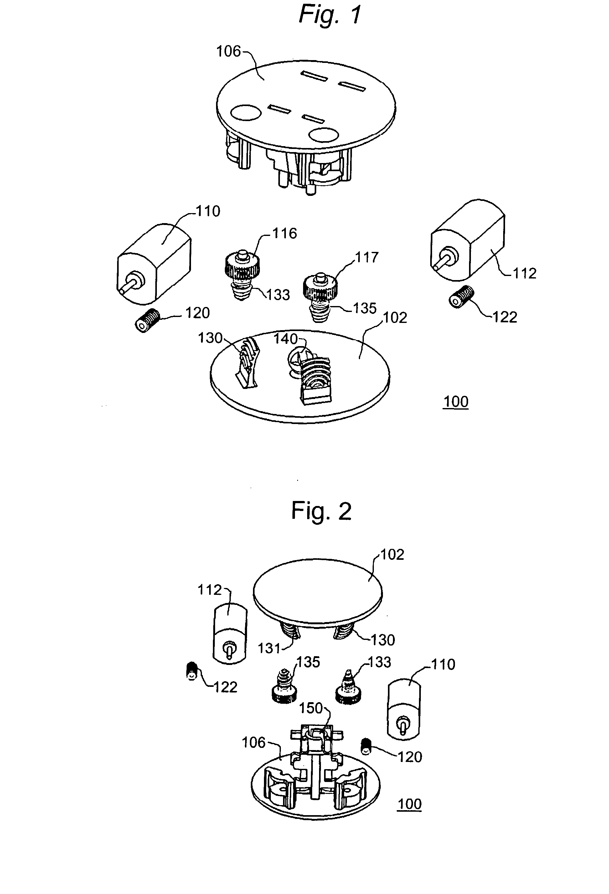
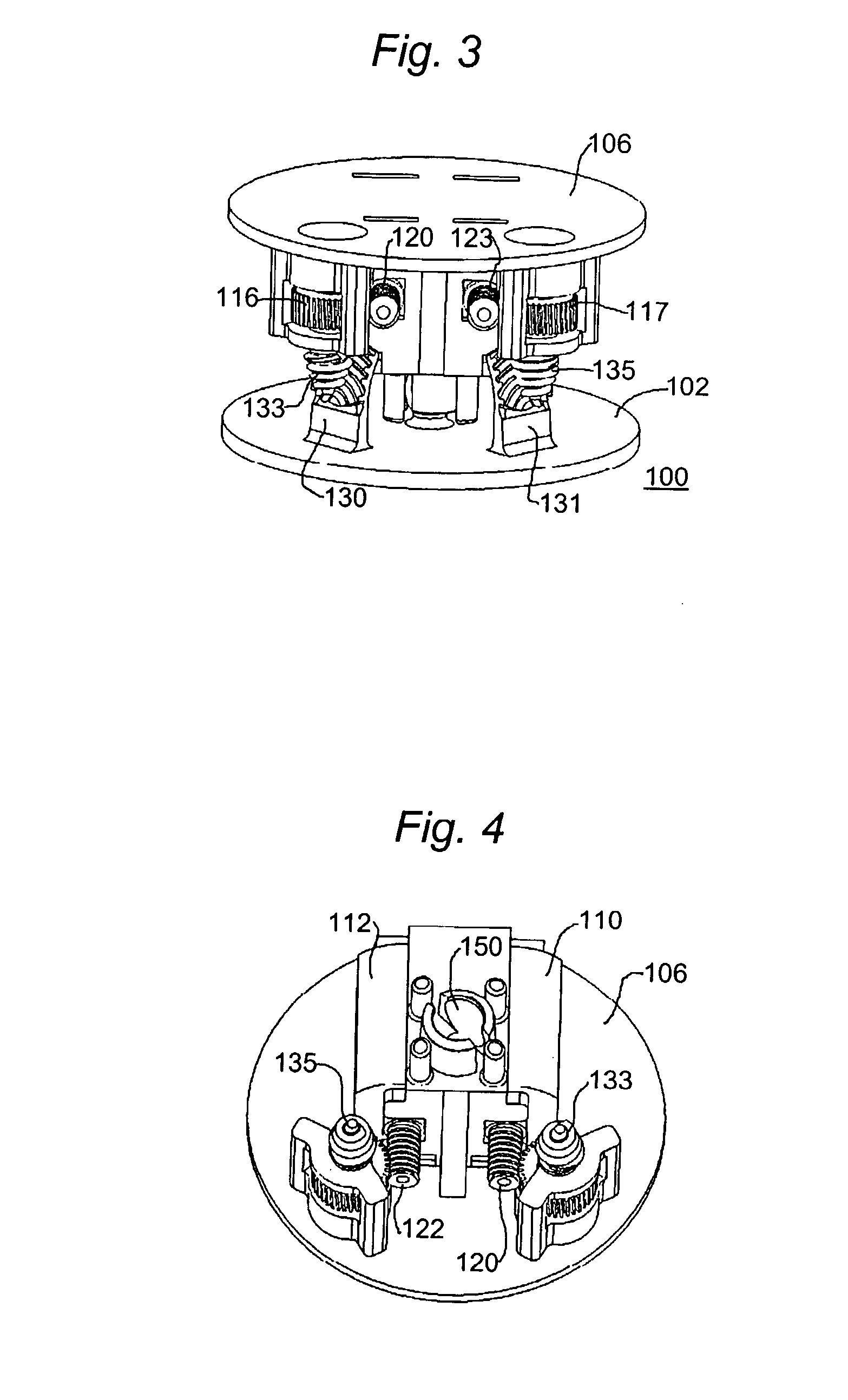
[0012] In one embodiment, the engagement between the worm drive element and the first spherical gear is arranged to disengage in response to the application of a force through the first spherical gear. In a rear view mirror embodiment of the invention, this feature permits manual orientation of the mirror.
[0022] Specific to transportation applications, the apparatus contains a flexible bellow-type structure that encases the assembly and prevent the motors and gear arrangements from being contaminated by environmental water and dust. Additionally, the assembly uses flexibility in the gear mounting structure to allow the gears to ratchet over one another if enough torque is present. This torque might represent the user manually repositioning the mirror in the event that one or more of the motors is inoperable. This torque might also represent a fixed object (frozen ice) that would block the mirror from rotating. This override feature would allow the motors to continue to rotate and avoid motor damage.
[0023] Several variations exist with this design that allow one motor to be used to drive both rotational axes. These variations employ an alternative actuator, that preferably simpler and of less cost than an additional or second motor, to physically move the motor and its associated worm, from one driving axis to the alternative driving axis.
[0026] A further embodiment eliminates the worm-gear-worm double reduction gear and uses the motor, with an associated worm, to drive the spherical gear directly for each axis.

Problems solved by technology

Known remotely adjustable outside mirror arrangements for vehicles are complex and are subject to failure, particularly when snow and ice are present.
Typically, numerous parts, including relatively fragile gear sections, are required to be incorporated within a mirror housing.

Method used


Image

  • Orienting Arrangement for Mirror or Light Source
  • Orienting Arrangement for Mirror or Light Source
  • Orienting Arrangement for Mirror or Light Source

Examples


embodiment 300

[0060]FIG. 9 is a simplified schematic representation showing a one-motor embodiment 300 constructed in accordance with the principles of the invention. As shown in this figure, a motor 310 is angularly displaceable to engage selectively with a first worm drive 316 and a second worm drive 318. The angular displacement of motor 310 is governed by the combination of a spring 320 and a shape-memory alloy (“SMA”) actuator wire (hereinafter “SMA 322”). The single motor 310 is coupled to one end of SMA 322, and the other end of SMA 322 is, in this specific illustrative embodiment of the invention, coupled to a stanchion (not shown in this figure) on the base (not shown in this figure). It is to be understood that any other suitable form of actuator, such as an electromagnet, can be employed in the practice of the invention, instead of SMA 322.

[0061]FIG. 10 is a simplified perspective representation showing the one-motor embodiment of FIG. 9. Elements of structure that have previously been...

embodiment 500

[0067]FIG. 15 is a simplified plan view of a further single motor embodiment 500 of the invention. As shown in this figure, a motor 510 is closely coupled to a drive arrangement 515 that may, in certain embodiments, constitute a worm drive. In other embodiments, however, drive arrangement 515 may constitute a resilient, friction coupled element.

[0068]FIG. 16 is a simplified isometric representation of the embodiment of FIG. 15 showing a greater degree of assembly in this embodiment, drive arrangement 515 may engage as a worm drive with partial gear 520, or may, in certain embodiment, couple as a resilient frictional element 521.


PUM


Abstract

An arrangement for orienting a device angularly, such as an outside rear view mirror for a motor vehicle, is provided with a back element on which the device to be oriented is installed. The back element has a first portion of a coupling element, which may be in the form of a ball, and a first spherical gear arranged concentrically in relation to the first portion of the coupling element. A base portion having a second portion of the coupling element, which may be a corresponding socket, engages with the first portion (the ball) of the coupling element. In addition, a motor having a rotatory shaft is installed on the base portion, and a worm drive element is installed on the rotatory shaft and arranged to engage the first spherical gear when the first and second portions of the coupling element are engaged with each other. The engagement between the worm drive element and the first spherical gear is arranged to disengage in response to the application of a force through the first spherical gear, and may include an intermediate structure, such as worm gear-worm combination element.

Description

BACKGROUND OF THE INVENTION [0001] 1. Field of the Invention [0002] This invention relates generally to arrangements for orienting optical devices, and more particularly, to a system for orienting an external rear view mirror for a motor vehicle. [0003] 2. Description of the Related Art [0004] Known remotely adjustable outside mirror arrangements for vehicles are complex and are subject to failure, particularly when snow and ice are present. Typically, numerous parts, including relatively fragile gear sections, are required to be incorporated within a mirror housing. There is a need for a remotely adjustable mirror arrangement for a motor vehicle that is simple to fabricate, and yet is reliable and sturdy using but a relatively small number of individual parts. [0005] It is, therefore, an object of this invention to provide a simple and sturdy rear view mirror arrangement for a motor vehicle. [0006] It is another object of this invention to provide an outside mirror arrangement for ...

Claims


Application Information

Patent Timeline
IPC IPC(8): G02F1/1335
CPCB60R1/072Y10T74/19014Y10T74/19684Y10T74/19047
Inventor HETRICK, JOEL A.ERVIN, GREGORY F.
Owner FLEXSYS
Features
  • Generate Ideas
  • Intellectual Property
  • Life Sciences
  • Materials
  • Tech Scout
  • Unparalleled Data Quality
  • Higher Quality Content
  • 60% Fewer Hallucinations
Learn More