Exposure apparatus, exposure method, and device manufacturing method

a technology of exposure apparatus and manufacturing method, which is applied in the direction of photomechanical treatment, printing, instruments, etc., can solve the problems of fluctuation of other aberrations, and achieve the effect of preventing the decline of throughput and efficient manufacturing of devices

Active Publication Date: 2007-12-20
NIKON CORP
View PDF16 Cites 21 Cited by
  • Summary
  • Abstract
  • Description
  • Claims
  • Application Information

AI Technical Summary

Benefits of technology

[0010] According to the first or the second aspect, when there is a shift in the center of the projection area accompanying modification of the projection magnification, the shift length is calculated, and position information for the exposure area to be exposed to the pattern is corrected. For example, by correcting the position of the substrate used in exposure processing based on the shift length, the mask pattern is transferred onto a prescribed position on the substrate. As a result, installation of an image shift optical element and / or fluctuations in other aberrations are avoided. Further, repeated measurements of the baseline value upon each modification of the projection magnification are reduced, and a decline in throughput can be prevented.
[0012] According to the third aspect, in the lithography process, for example declines in throughput can be prevented, and devices can be manufactured efficiently.

Problems solved by technology

In technology of the prior art such as that described above, when an optical element to correct image shift is provided and is inclined to correct image shift, there is the possibility of fluctuation of other aberrations.

Method used


Image

  • Exposure apparatus, exposure method, and device manufacturing method
  • Exposure apparatus, exposure method, and device manufacturing method
  • Exposure apparatus, exposure method, and device manufacturing method

Examples


Embodiment Construction

[0021] Below, embodiments of an exposure apparatus, exposure method, and device manufacturing method of the invention are explained, referring to FIG. 1 through FIG. 7.

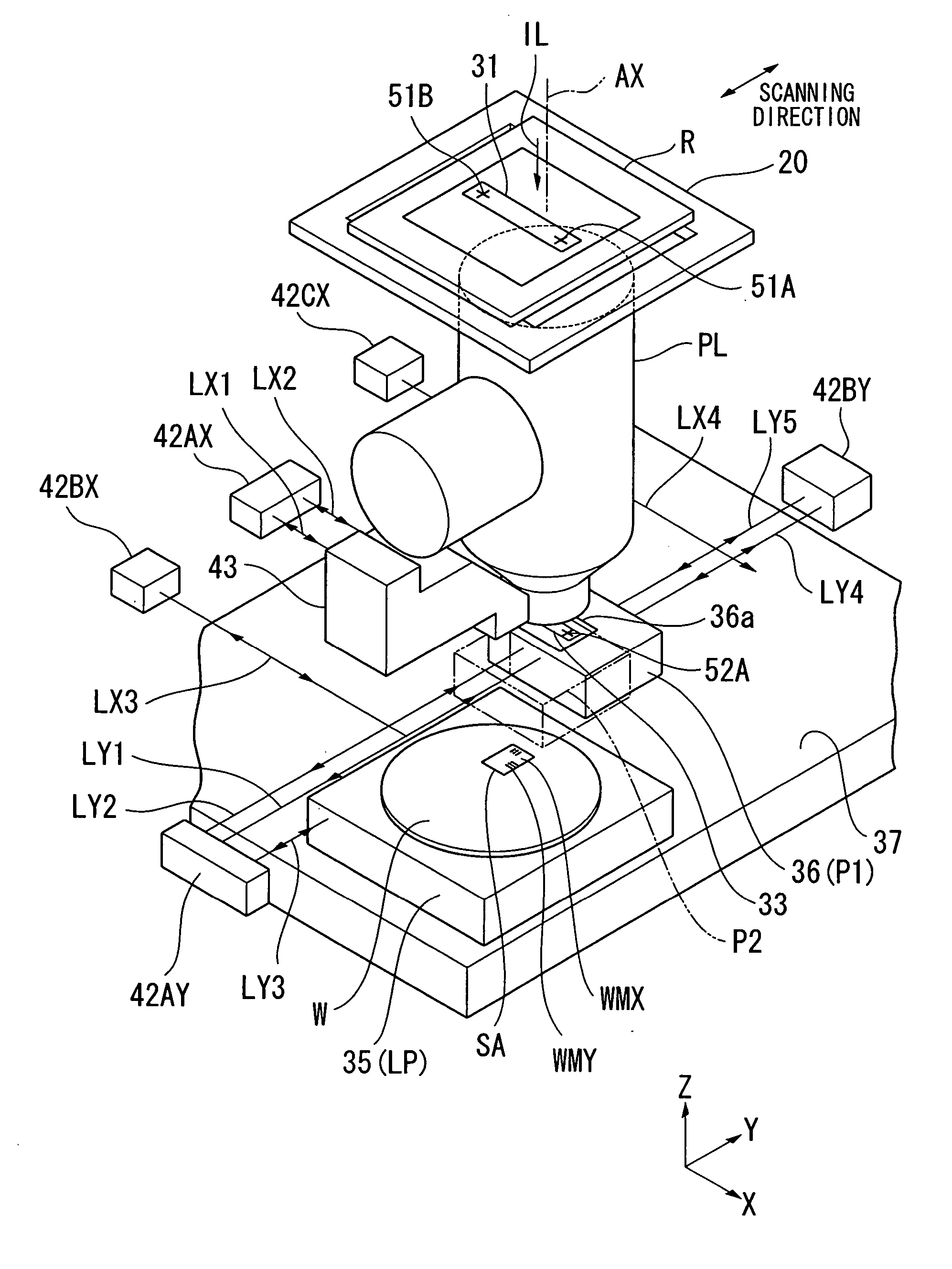
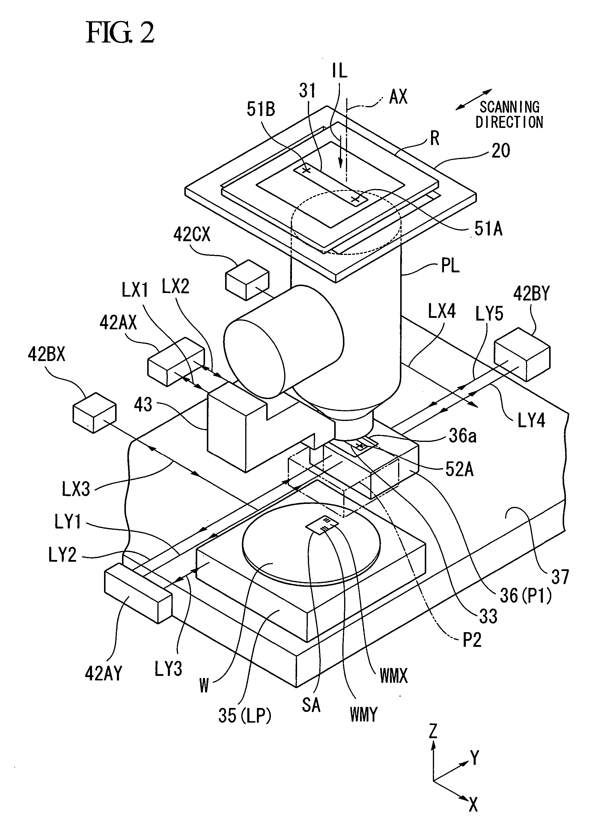
[0022] In the present embodiment, the invention is applied to a step-and-scan type projection exposure apparatus which uses a catadioptric system as the projection optical system.

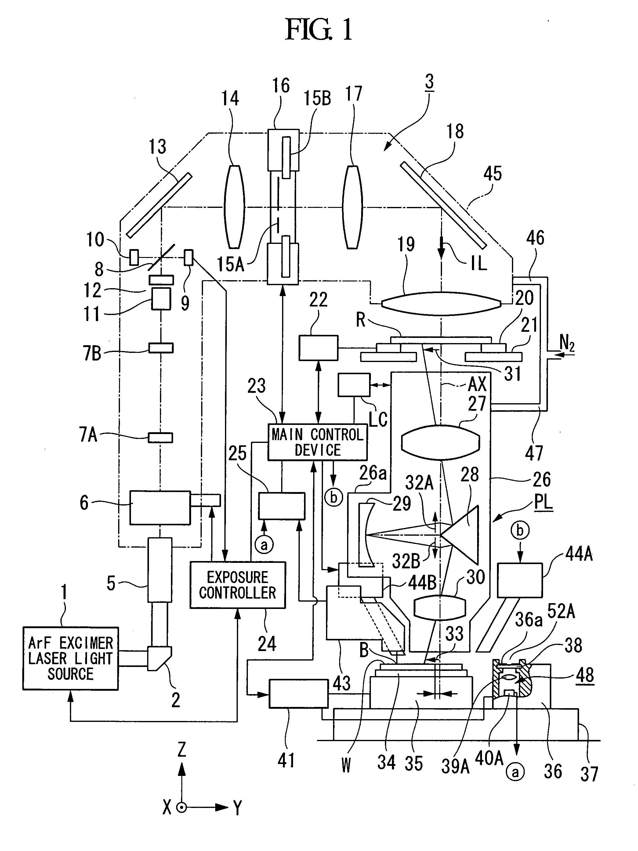
[0023]FIG. 1 shows in summary the configuration of a projection exposure apparatus according to the embodiment; in FIG. 1, the chamber which houses the projection exposure apparatus is omitted. In FIG. 1, an ArF excimer laser light source 1 (oscillation wavelength 193 nm) is used as the exposure light source. As the exposure light source, lasers which emit laser light in the ultraviolet range in the oscillation step, such as a KrF excimer laser (wavelength 248 nm) or an F2 laser (wavelength 157 nm), or devices emitting high-harmonic laser light substantially in the vacuum ultraviolet range, obtained by wavelength conversion of near-infrared...


PUM


Abstract

An exposure apparatus includes a projection optical system, which projects a pattern of a mask onto a prescribed exposure area on a substrate at a prescribed projection magnification. The optical axis center of the projection optical system is set to a position different from that of the center of the projection area onto which the pattern is projected. The exposure apparatus further includes a magnification modification device, which modifies the projection magnification of the projection optical system; a calculation device, which calculates a shift length of the center of the projection area associated with modification of the projection magnification; and a correction device, which corrects the position information of the exposure area based on the shift length of the center of the projection area.

Description

CROSS-REFERENCE TO RELATED APPLICATION [0001] This application claims priority to Japanese Patent Application No. 2006-118004, filed Apr. 21, 2006, the contents of which are incorporated herein by reference. BACKGROUND OF THE INVENTION [0002] 1. Field of the Invention [0003] This invention relates to an exposure apparatus, an exposure method, and a device manufacturing method. [0004] 2. Description of Related Art [0005] There exist exposure apparatuses which employ catadioptric type projection optical systems using a concave mirror, such as that described for example in Japanese Unexamined Patent Application, Publication No. H06-132191. In this type of exposure apparatus, it is known that when an area shifted from the optical axis of the projection optical system is used as the exposure area, if the projection magnification is changed, the center of the projected image is shifted (image shift). Japanese Unexamined Patent Application, Publication No. 2004-145269 discloses technology ...

Claims


Application Information

Patent Timeline
Patent Type & Authority Applications(United States)
IPC IPC(8): G03B27/52
CPCG03F7/70875G03F7/70783G03F7/70258G03F7/70225G03F7/70266G03F7/70308G03F7/70516G03F7/706G03F9/7088
Inventor SUZUKI, KOUSUKE
Owner NIKON CORP
Why Eureka
Try Eureka